Wide band moderate power dummy loads
Good high frequenty performance with wire wound resistors.
"Noninductive" wire-wound resistors are capable of handling more power than the composition types, but as a general rule are not sufficiently nonreactive to make predictable dummy loads at the higher frequencies. Here are some easily-built dummies using a simple method of reactance compensation, good for frequencies through the 144-Mc. band and transmitter power outputs up to 40-80 watts.
Amateurs generally do not know how helpful a dummy load can be in the testing and adjustment of a transmitter. Commercial radio services use them for many purposes in ways that amateurs could imitate, and the purpose of this article is to discuss these uses and to show the construction of several adequate low-cost dummy antennas.
Several uses of the dummy antenna are tracing TVI, testing transmitters, testing s.w.r. bridges, and testing transmission lines. This makes a fairly complete list, but there are also other benefits, for familiarity with the effects that go into the design of a good dummy antenna makes the use of resistors at radio frequencies a much less frustrating affair. Limiting the discussion to resistors that will handle some power and that amateurs can afford simplifies the discussion and allows space for both construction and theory talk.
Wire-wound resistors
When power resistors are mentioned, the natural first thought is the wire-wound style that has been used so long for bleeder and voltage-drop ping purposes. These resistors are available in a wide range of values, from a few ohms to thousands of ohms, in power ratings of a few watts to over 250 watts. Most of them are not satisfactory for easy r.f. use, being wound like an ordinary tuning coil, one turn beside the other, all in the same direction. There is, however, one type of resistor(1) made with a ceramic-insulated wire that permits winding layers on top of each other in opposed directions, without shorting turns. These relatively inexpensive resistors were used in the dummy antennas to be described because of their availability and fairly good frequency characteristics. While of a type called "non-inductive," these resistors (like any other component) will show capacitance and inductance as part of their impedance. Their use is usually limited to a few megacycles if neither inductance nor capacity effects are permissible.
There are other types of resistors, some better and some worse for use at radio frequencies. The better resistors are usually of the film type (a metal film deposited on glass or some other insulator) but are more expensive and harder to obtain. Commercial dummy antennas use this form of resistor successfully to frequencies higher than 3000 megacycles, but the cost for power ratings as high as the units described here may be ten to twenty times greater.
Many other types of resistors have been used for dummies, the most common probably being the incandescent light bulb. While the light bulb certainly does change r.f. energy to heat, it shows drastic change of resistance with different power inputs. The ordinary light bulb, cold, has only 7 to 10 per cent of the resistance it has at normal operating temperature. Thus in the course of transmitter tune-up a 100-watt bulb might change from a value of 10 to 130 or more ohms. Thin is probably the most frustrating thing that can happen when it is desired to check changes in adjustments. (Something must stay constant to permit a comparison between two conditions.) A much better dummy was described by Grammer a few years ago using the heating element of a flatiron.(2) The r.f. characteristics were fairly good, but the resistance was quite low and a matching network was required to bring it up to a desired level. This required major retuning for each band. Occasion ally other dummies have been described or offered for sale, but there is usually high cost, little application data, or poor availability.
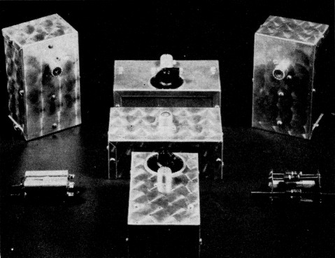
Some of the wide-band dummy resistors developed in the course of the investigation. (Left to right, back row, 100 to 180 Mc, 0-80 Mc, 30-80 Mc; center, composite 0-175 Mc; front, 300 ohm 50 Mc. balanced, early 0-80 Mc, 100 ohm experimental.
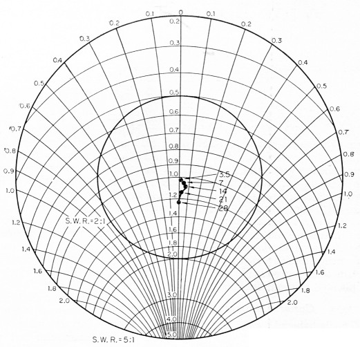
Fig. 1. Impedance characteristics below 30 Mc. of the dummy shown in Fig. 2; capacitor dial set at 30 (100 division scale, with zero at minimum capacitance of the HF 50 capacitor used). This and the other charts in this article are presented in the form of Smith charts, with the actual impedance values normalized to the design value (50 ohms in the case above). Points in the area to the right of the vertical axis represent impedances having an inductive component; those in the lefthand area are capacitive.
With these items in nalnd, an examination was made of the possibility of a home-assembled dummy antenna that had predictable characteristics. While working for Sprague, I had had many ham questions on the Sprague Non-inductive Koolohms referred to me. Repeated measurements showed that the most constant r.f. values were obtained in the 200-ohm units in any wattage range. I do not know why this particular value is more predictable in the megacycle region; it merely is. The resistance is fairly close to the d.c. value, with little reactance, near 3.5 megacycles; but inductive effects and a rising resistance appear by the time 7 Mc. is reached.
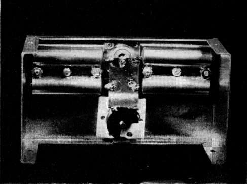
Fig. 2. Zero to 30 Mc. dummy using special resistor holder (see text) and shunt variable capacitor compensation. Note copper sheet connecting res'ktors to variable capacitor and Coax connector. Resistors .sre grounded at outside ends. This dummy is useful to 80 Mc.. (v.s.w.r. = 1.6) with the capacitor set at 18.
Wide-band compensation of inductance
The resistors were measured on a Boontoon RX Meter giving r.f. readings of parallel resistance and capacitance. (If an item was inductive, capacitance was added; if capacitive, capacitance was subtracted.) It was early observed that the necessary added capacitance stayed quite constant to 14 Mc. and only dropped moderately going to 30 Mc. Resistance rose somewhat, but not enough to be seriously objectionable in terms of s.w.r. A mathematical cause was found for this action (see Appendix) and it was found experimentally that a fixed parallel capacitor could do a fine job of compensation through 30 and perhaps 60 Mc., depending on the dummy requirements.
The rising resistance characteristics were also put to work. All experimental investigation was aimed at a 50 ohm dummy made from 200 ohm 10 watt noninductive Koolohms, so since the resistance rose approximately 50 per cent at 50 Mc., six resistors instead of four were paralleled, resulting in an effective dummy between 30 and 80 Mc.
At this point, Sprague Products Company President Harry Kalker became interested in the project and had some special resistor-twinholders made for the resistors .3 The holder capacitance with one end of the resistor grounded was just sufficient to make the resistor bank of six become fairly well compensated from 30 to 80 megacycles. At lower frequencies, the bank of four was equally well compensated.
Going much above 70 Mc., the resistors began to look capacitive, so a series inductance in the form of a hairpin was added. This cancelled much or all of the capacitive effect and permitted use of a shunt capacitor at the terminals to cancel the inductive effect and step up the apparent resistance. Actually all that is being done in this form of the dummy and the other dummies is to find the effect of frequency on the resistor and then find some simple way of correcting for it. There's no magic involved - just a process of measuring, figuring, and trying. Fortunately, the results seem reproducible and the designs may be duplicated without further thinking.
Construction and results
The first thought was that the dummy resistors had to be able to dissipate safely a reasonable amount of power. Power is generally an average effect over a brief period of time, for it takes time for any object to heat to the danger point. The Koolohm construction is good under overload and these resistors may be run for thirty-second periods at twice rated power without damage if they are allowed to cool to room temperature before further use. (It should be stated that "Koolohm" is a trademark and that the resistors generate the same number of heat calories as any other resistor at the same power.) The power rating for each resistor, therefore, is ten watts continuous and twenty watts for thirty-second periods. Thus a bank of four would have a rating of 40 watts continuous and 80 watts for 30 seconds. Higher powers could probably be used for briefer periods, but there is no data on this. The metal resistor clamps are not believed able to increase power ratings, for what is gained in heat dissipation is considered lost by having other resistors close by.
Capacitors used in compensation are required to carry fairly high currents at the higher frequencies. While many excellent fixed capacitors are made, their "special order" nature and resulting high cost made use of a variable air capacitor desirable. The Hammarlund HF-50 was chosen as being generally available at reasonable cost.
To be widely useful, a dummy should be shielded. No really good shield boxes seem generally available, so the Bud 3006 Minibox was chosen as it had enough volume to permit easy layout and was small enough to be wrapped in aluminum foil when additional shielding was necessary. Extra screws were added to some of the dummies to improve shielding but were inadequate for really critical use such as TVI testing.
Last, but very important, is the type of wiring used. Generally, sheet copper was used to make connections because wide conductors have much less inductance than round wires. The sheet conductor has another useful characteristic: an amazing percentage of the resistor heat can leave by way of the leads, and if the resistors are connected by very short leads to a large area of copper they operate much cooler.
The first dummy built was intended to cover the range from d.c. to 30 Mc, and the happy results obtained are plotted on the impedance chart of Fig. 1, where the results are expressed as fractions of the desired 50 ohms. Layout seems uncritical, for a later dummy (Fig. 2) with a different layout duplicated these results even to the readings of the compensation capacitor. Incidentally, each of the points under 30 Mc. may be perfectly compensated for reactance by resetting the compensation capacitor.
A fuller understanding of the characteristics of the resistor alone is necessary when aiming at higher frequencies. Measurements without a shield are presented in Fig. 3. This result was obtained with a single resistor tested with one end grounded and the body mounted about 3 inch from a grounded sheet of metal, lead length being about ¼ inch. Here it is apparent that the resistor appears inductive, with increasing resistance to the upper limit of measurement.
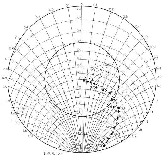
Fig. 3. Impedance characteristics of a Sprague 200 ohm 10 watt noninductive resistor parallel with and ¼ inch from a ground plane, with ¼ inch leads and one end grounded. Values normalized to 200 ohm.
As earlier hinted, the easiest way to compensate for the rising resistance is to pretend that it is not there by paralleling larger numbers of the resistors. Thus, in the dummy of Fig. 4, six resistors are paralleled (instead of four) to give a "50"-ohm resistance in the vicinity of 50 Mc. The capacitance supplied by the resistor holders (or foil wraps if the holders are not available) does a quite acceptable job of reactance cancellation (Fig. 5), although if perfect reactance cancellation is required, the values shown in the table accompanying the figure may be used.
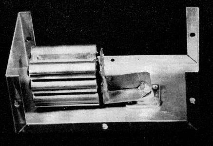
Fig. 4. Thirty to 80 Mc. 50-ohm dummy resistor. Note the use of six paralleled 200-ohm (nominal value) resistors to obtain 50 ohms.
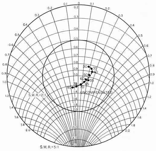
Fig. 5. Impedance characteristic of the 30-80 Mc 50 ohm dummy without further compensation. The shunt capacitance required for complete cancellation of the reactive component of the impedance is as follows:
| Frequency, Mc | Capacitance, pF |
|---|---|
| 30 | 27.9 |
| 35 | 26.5 |
| 40 | 21.1 |
| 50 | 13.8 |
| 55 | 10.8 |
| 60 | 6.4 |
| 65 | 5.3 |
| 70 | 2.7 |
Aiming at still higher frequencies (100 to 180 megacycles), extremely high resistances must be transformed down to the vicinity of 50 ohms. While impedance matching networks may be used having lumped capacitors and inductors, an attempt was made to see whether good compensation could be obtained with just a piece of wire used as a transmission line (Fig. 6). The characteristics resulting are such that, without further compensation, an acceptable dummy is produced between 100 and 135 megacycles (Fig. 7). Added capacitive compensation will take care of frequencies to 170 megacycles.
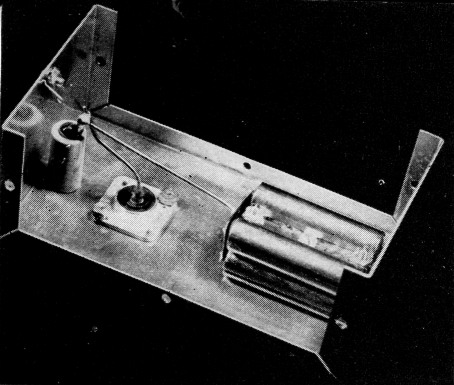
Fig. 6. Dummy for use between 110 and 170 megacycles. Note the "hairpin" of wire that provides impedance transformation of actual resistance to a value nearer 50 ohms.
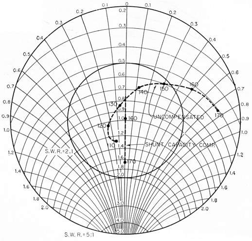
Fig. 7. Impedance characteristics of the 110-170 Mc. 50-ohm dummy, w!th and without capacitive compensation. Required values of compensating capacitances are as follows:
| Frequency, Mc | Capacitance, mid. |
|---|---|
| 140 | 5.4 |
| 150 | 14.3 |
| 160 | 19.0 |
| 170 | 17.1 |
The use of capacitive compensation may strike some readers as being either cumbersome or expensive. Actually, capacitors are probably the least expensive and most predictable adjustable energy storage devices. The use of shunt capacitive compensation as advocated in this article permits use of a grounded-rotor capacitor such as the common variable, with attendant ease of mounting and freedom from hand-capacity effects. Small capacitors should be used, naturally, for large capacitors do have a tendency to look like transmission lines at high frequencies.
Composite Resistors
Composition resistors as well as wire-wound types were investigated in the search for a good dummy. The major drawbacks of the type commonly available are inability to handle high power and, particularly in the high-resistance ranges, decreasing resistance and an increasing capacitive reactance.
Plotting the radio-frequency characteristics of these resistors in the fashion of the dummies, it became apparent that over a very wide frequency range composition resistors exhibited almost exactly opposite variations to the noninductive wire-wound variety. The obvious step was to parallel composition and wire-wound resistors. This was initially done with a single 200 ohm 10 watt noninductive wire-wound resistor and five 1000 ohm 2 watt composition resistors to make a 100 ohm nominal 20 watt resistor. The composite resistor still exhibited a small amount of inductance at thirty megacycles, but this was easily compensated by the addition of 1.1 mA in parallel in the form of two small series NP0 ceramic capacitors.
The final form of the composite dummy was a 50-ohm 40-watt unit (Fig. 8) constructed in the standard case selected for this series of dummies. Good characteristics resulted (Fig. 9) although it should be emphasized that composition resistors are sensitive to power overloads, so such a combination should not be run at more than half of the total wattage if close long-term stability is desired. If less than the best stability is satisfactory, full rated power may be run for fifteen seconds or so at frequencies under 30 megacycles.
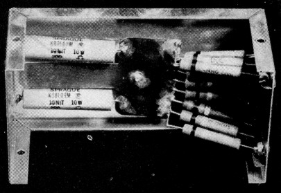
Fig. 8. Composite 50-ohm dummy made up of two 200-ohm 10-watt noninductive wire-wound resistors and ten 1000-ohm 2-watt composition resistors. The tongue between the wire-wound resistors may be bent to furnish capacitive compensation. The coaxial connector is under the copper sheet.
Use of dummy resistors in the ham station
Most hams wrongly think of a dummy as a seldom-used device whose only purpose is to burn up unwanted power. Instead, dummy resistors, dollar for dollar, are probably among the most useful station accessories, next to a monitor and s.w.r. bridge.
Dummies should be used to check a transmitter before putting it on the air. This is commonly done by connecting to the transmitter a dummy whose impedance is near the actual antenna or transmission line input impedance. In the case of first-time operation of a transmitter, this is obviously necessary to prevent an unexpected load from resulting in damage to the equipment. The average amateur should use this dummy to peak up each transmitter stage at an operating frequency before attempting transmission, as well as for experimentation. Those with small children will also find it useful to reset disturbed dials correctly when curious fingers have "worked with radio like Daddy." In any case, the law requires (Section 12.151) that "... each amateur station shall be operated with good engineering and good amateur practice," and good engineering practice prohibits putting an unnecessary signal on the air.
TVI investigation requires the use of a dummy antenna that is well shielded, for harmonics leaking out of a poorly shielded dummy can cause TVI as easily as harmonics leaking out of a poorly shielded transmitter. Any of the dummies described in this article if well wrap7:ed in aluminum foil are as tight to r.f. as the best transmitters can be expected to he. If such a dummy is used for the transmitter load and TVI persists, interference power is leaking through the transmitter case or coming out on key, mike, or power leads.
Coaxial cable is often suspected of breaks when used to feed an antenna that loads poorly. A dummy placed at the far end of the cable will show a low s.w.r. and normal loading on a good piece of cable, while either open or shorted cable will have a high standing-wave ratio.
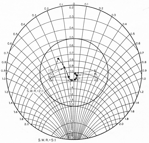
Fig. 9. Impedance characteristics of the composite 50-ohm dummy resistor pictured in Fig. 8. Wide-band characteristics of this dummy permit its use from zero to 175 Mc. in most applications, though care must be token to avoid overload.
Antenna s.w.r. bridges are readily checked with dummy resistors. Frequently an antenna bridge (being a new and expensive piece of station equipment) is first suspected when an unusual loading condition is encountered. Use of a dummy load instead of an antenna rapidly answers the question, for a bridge showing a low s.w.r. on the dummy is good and the trouble, is elsewhere.
Summing up, a dummy will not necessarily produce a better or stronger signal, but it will make attaining a good strong signal a quick, easy and legal job.
Acknowledgments
This work was done while the writer was an employee of Sprague Electric Company and their assistance and that of Sprague Products Company is acknowledged and appreciated.
Appendix
The possibility of wide-band compensation of slightly inductive resistors with shunting capacitors is shown in the following way:
1) Assume a resistance Rs in series with an inductive reactance Xs.
2) The parallel equivalent of Xp is ![]()
3) If Xs is much less than Rs,
![]()
4) Where an inductance is paralleled with a capacitance, neither appears to be in the circuit when the capacitive reactance is equal to the inductive reactance. Thus the condition for cancellation of the inductive effect occurs when the parallel inductive reactance Xp equals some parallel capacitive reactance ![]() which is another way of saying
which is another way of saying
![]()
or
![]()
5) This last expression has no frequency term in it, showing that a small inductive reactance can be nearly eliminated at all frequencies by a single fixed capacitor.
Notes
- Sprague Products Company NIT and NIS series.
- "Adjustable dummy antennas," QST, March, 1951.
- It is not known at this time whether these will be sold, but they can be duplicated electrically by wrapping all but one end of each resistor in aluminum foil.
David T. Geiser, WA2ANU.