Input impedance and fed-through power in grounded-grid amplifiers
Interest in the grounded-grid power amplifier has been high because the circuit offers one way to make use of otherwise-excessive power output from a driver. Another feature is low input impedance and the accompanying possibility of eliminating a tuned driver-coupling circuit. Simple methods of calculating the fed-through power and input impedance are discussed here.
The operation of the grounded-grid amplifier circuit shown in Fig. 1A can be understood without much difficulty by making use of a simple equivalent circuit. The circuit at A is intended merely to be representative (even the d.c. feed arrangements have been omitted); any suitable coupling circuits could be substituted for the tuned circuit, L1C1, by means of which the driving power is applied to the grid-cathode circuit of the tube, and for the parallel-tuned output tank, L2C2. Also, it will be taken for granted in the following discussion that the plate-to-cathode capacitance of the amplifier tube is so low that no appreciable amount of r.f. energy can be fed through it either from the input side to the output side or in the opposite direction.
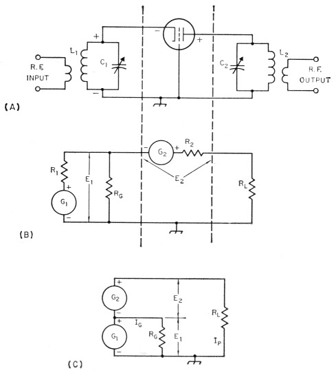
Fig. 1. Equivalent circuit of the grounded-grid amplifier. As shown in the simplified equivalent at C, the driver and amplifier may be considered as two generators in series with the power-consuming load resistance. The voltages of these two generators are in phase, as indicated by the instantaneous polarity signs on the circuits.
In the equivalent circuit at B the driver and coupling circuit L1C1 have been replaced by an r.f. generator, G1, having an internal resistance R1, and developing a voltage E1 at its output terminals. E1 is the r.f. voltage applied between grid and cathode in the actual amplifier. The resistance Rc is present to account for the grid losses in the amplifier under the chosen operating conditions - in other words, with E1 applied to R0 the power lost in Rc is equal to the driving power (WG) that would be needed if the tube were being operated in the familiar grounded-cathode circuit.
An equivalent generator, G2, having an internal resistance R2 and generating an r.f. output voltage E2, also replaces the amplifier tube of Fig. 1A. E2 is the r.f. voltage that appears between cathode and plate under the assumed operating conditions. In the third section of the equivalent circuit, Rr, replaces the tuned tank circuit. Rr, is the load resistance as seen by the amplifier circuit - the transformed (by the tank) value of the actual load resistance. The actual load may be a transmission line or any of the devices that commonly absorb or transfer power from transmitting circuits.
E1 and E2 are the terminal voltages, rather than the generated voltages, of G1 and G2, respectively. Under a given set of operating conditions they may be considered to be constant. When this is so the generator internal resistances R1 and R2 can be ignored. Thus the equivalent circuit can be simplified still further to the one shown at C in Fig. 1.
Equivalent-circuit operation
With this equivalent circuit it is readily possible to calculate both the total power required from the driver and the impedance of the amplifier input circuit as seen from the driver. Fig. 1C is obviously a rather simple Ohm's Law circuit. The power in RL is supplied by Ch and G acting in series, thus the total r.f. voltage across RL is the sum of El and E2. Since Gl and G2 are in series with RL, the same r.f. current flows through all three. This current, which we will designate I,,, can be found from the known power output of the amplifier tube:
![]()
Ip is the effective value of the fundamental-frequency r.f. current that flows through RL (not to be confused with d.c. plate current), and Wp is the rated output of the amplifier tube.
The power contributed by the driver to RL (fed-through power) is
Fed-through power = E1 × IpThe resistance seen by the driver - that is, the input impedance of the amplifier - is simply the driver voltage divided by the total r.m.s. driver current. The total driver current can be found easily, knowing the total driver power and the voltage El. The total driver power is the sum of the fed-through power and the grid losses in the amplifier (the "normal" driving power). Thus the total driver current is
![]()
The input impedance of the amplifier is then
![]()
In most cases, WG will be fairly small compared with E1Ip; that is, considerably more power is fed through to the output circuit than is consumed in the grid circuit of the amplifier tube. For a given set of operating conditions, no more power is actually lost in the grid with grounded-grid operation than with grounded-cathode operation.
Fed-through power
The amount of fed-through power is controlled by the relationship between the grid-cathode driving voltage, E1, and the tube output voltage, E2. The larger the ratio of E1 to E2, the larger the proportion of the total output power that is supplied by the driver.
It follows that a tube requiring a relatively large driving voltage as compared with output voltage - that is, a low-44 tube, in the case of a triode - will have greater fed-through power than one (high-µ) that takes relatively little driving voltage. This assumes that both types operate at the same plate voltage and develop the same output power at the same plate current. It does not mean that the low-µ tube is "harder to drive" than the other, since both may have the same, or approximately the same, actual loss in the grid.
Also, for a given tube operating at a specified plate voltage, a choice of operating conditions that requires a larger driving voltage will result in a greater amount of fed-through power. If there is no limitation on grid bias the fed-through power can be increased simply by increasing the negative bias and increasing the driving voltage to give the same amplifier plate current. In general, this can be done only in Class C operation since the bias cannot be set; beyond cut-off in the Class B amplifier.
In any given setup the amount of fed-through power depends on the actual plate loading as represented by the load resistance RL. Within the normal limits of operating conditions as determined by, for example, desirable values of amplifier plate efficiency, increasing the loading (by reducing RL) will result in more power being fed through, since heavier loading will mean increased Ip. The converse also applies. The relationship is not linear, however, since the amplifier tube does not generate a constant terminal voltage with varying load resistance; also, the optimum driving voltage depends on the loading so the driving voltage, too, should be changed when the load resistance is changed. Hence calculations are usefully accurate only when a specific set of operating conditions is selected.
Input impedance
To a first approximation (neglecting the effect of grid losses) the amplifier input impedance is equal to E1/Ip. Thus it will be larger if E1 is increased while Ip is held constant, or will be smaller if 4 is increased while E1 is held constant. In a general way, this means that if the plate current of a given amplifier tube is held constant while the grid bias and driving voltage are varied (assuming no marked changed in plate efficiency), high bias and high driving voltage will result in a relatively high input impedance, while small bias and low driving voltage will give a relatively low input impedance.
From this we can conclude that low-μ triodes and Class C operation will result in higher input impedance than high μ triodes and Class B operation, other things being equal. It is apparent, too, that a low value of input impedance will, in general, be associated with relatively low values of fed-through power.
These generalizations have to be hedged with the "relatively" and "other things being equal" qualifications, since much depends on the actual operating conditions and the characteristics of the amplifier tube used. They are good, however, for comparing amplifiers operating at the same plate voltage, plate current, and plate efficiency.
The grid loss, WG, is not the major factor in determining the input impedance, but this does not mean that it is always - or even usually - negligible. Neither is it a constant element in the total driving power, since it will depend on the grid bias, driving voltage, loading, and the amplifier tube. It causes the input impedance to be lower than calculations based on fed-through power alone would indicate, since the r.f. grid current is added to the driver's contribution to the r.f. output current to make up the total driver current.
The input impedance, like the fed-through power, depends on the plate loading. Lighter loading means smaller I, and hence higher input impedance, and vice versa. If a grounded-grid amplifier is used with the object of providing a reasonably good match for a coaxial line without a tuned input circuit, the operating conditions must be chosen appropriately and adhered to strictly.
Linear amplifiers
So far, the discussion has been based on the assumption that E1 and E2 have fixed values determined by the choice of operating conditions. When the amplifier is a "linear" - i.e, one capable of amplifying a modulated signal without introducing appreciable distortion - both E1 and E2 can vary from zero to some predetermined peak-envelope value. (However, most other operating conditions, such as plate voltage, bias, tuning and loading, are held constant in linear operation.)
By definition, a linear amplifier is one in which the ratio between the output voltage and driving voltage is constant regardless of the amplitude of the driving voltage. That is, E2 = NE1, where N is a fixed number for any value of E1 from zero to some maximum value determined by the permissible distortion at peak output. In the linear amplifier case E1 is a modulated voltage, and because of the fixed ratio between E2 and E2, E3 is modulated identically. The total output voltage, which is the sum of the two, is also modulated identically. Linear operation is accomplished by appropriate choice of operating conditions for the tube, these conditions being basically the same as with a grounded-cathode circuit.
In other words, the equivalent circuit is also valid in the linear amplifier case. The principal difference in the approach to finding numerical values is that the variability of RG with driving voltage has to be included if a complete picture of the input impedance over a modulation cycle is wanted. However, the major advantage of the grounded-grid circuit as a linear amplifier lies in the fact that it has built-in "swamping" because of the fed-through power. Variations in input impedance tend to be minimized, as compared with grounded-cathode operation, because the percentage variation in the load on the driver is held to a relatively low value. It will usually suffice to base calculations on peak-envelope conditions. At lower levels of excitation the input impedance will rise, with most tubes, since the grid loss will decrease more rapidly than the fed-through power as E1 is progressively reduced from the peak-envelope value. In any case, the maximum possible variation in input impedance can be found from the figure calculated from peak-envelope conditions with the grid loss included, as compared with a figure calculated by neglecting grid loss entirely and using only the fed-through power.
Practical calculations
Most of the quantities used in the simple calculations outlined above can be found in data furnished by the tube manufacturers. Usually there is one conspicuous exception: the r.f. output voltage of the tube, designated E2 in this discussion. An acceptable approximation to it can be found by the following method:
- Find the d.c. plate voltage, grid bias voltage, and peak grid signal voltage from the selected set of published typical operating conditions.
- Subtract the grid bias voltage from the peak grid signal voltage. The result is approximately the minimum instantaneous plate voltage, since recommended operating conditions usually will be based on equal values of peak positive grid voltage and minimum instantaneous plate voltage.
- Subtract the result found in (2) from the d.c. plate voltage. The difference is the peak plate voltage swing.
- Multiply the result of (3) by 0.707 to obtain the r.m.s. value. This is the figure to be used for E2.
E1 is of course the r.m.s. value of the grid signal voltage; that is, 0.707 times the peak grid voltage usually given in the published data.
An 811-A operated as a Class C amplifier will serve as an example. Typical operating conditions as given by the tube manufacturer include the following:
| Plate voltage | 1500 volt |
| Grid bias | -70 volt |
| Peak r.f. grid voltage | 175 volt |
| Plate current | 173 mA |
| Driving power (Wg) | 7.1 watt |
| Power output (Wp) | 200 watt |
Using the above method of estimating, the minimum plate voltage is 175 - 70 = 105 volt, and the peak plate-voltage swing is 1500 - 105 = 1395 volt. Then
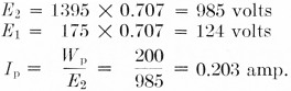
Fed-through power = E1 × Ip = 124 × 0.203 = 25.2 watt
Total power from driver = 25.2 + 7.1 = 32.3 watt.
![]()
![]()
Wout = 200 + 25.2 = 225 watt.
Notice that no use is made of the d.c. plate current in these computations. It was included in the list simply as a reminder that the loading must be adjusted to give this value of d.c. plate current in order that the calculated values of fed-through power and input impedance may be realized.
Table 1 shows the results of calculations of the same type on three sets of operating conditions for the 811-A and one set for the 812-A. Experimental measurements on setups using these tubes have verified the calculated values of fed-through power and input impedance.
| Published Operating Conditions | 811-A Class B* | 811-A Class C | 812-A Class C | |
|---|---|---|---|---|
| Plate Voltage | 1250 | 1500 | 1500 | 1500 |
| Grid Bias, volt | 0 | -4.5 | -70 | -120 |
| Peak Grid Voltage | 87.5 | 85 | 175 | 240 |
| Plate Current, mA | 175 | 156 | 173 | 173 |
| Driving Power, watt | 3.0 | 2.2 | 7.1 | 6.5 |
| Power Output, watt | 155 | 170 | 200 | 190 |
| Calculated | ||||
| E1 volt | 62 | 60 | 124 | 170 |
| E2 volt | 825 | 1020 | 985 | 975 |
| Ip A | 0.188 | 0.166 | 0.203 | 0.195 |
| Fed-through Power, watt | 11.6 | 10 | 25.2 | 33 |
| Total Power from Driver, watt | 14.6 | 12.2 | 32.3 | 39.5 |
| Ip + Ig A | 0.236 | 0.204 | 0.260 | 0.232 |
| Input Impedance, ohm | 252 | 284 | 477 | 733 |
| Total Output, watt | 167 | 180 | 225 | 223 |
* Values given are for one tube, taken from audio data.
When tubes are used in parallel the values (for one tithe) of plate current, grid driving power, fed-through power, and power output should be multiplied by the number of tubes. The figure for the input impedance should be divided by the number of tubes.
Screen-grid tubes
The methods described above can be applied to published operating data for screen-grid tubes in similar fashion, provided the r.f. screen return is made to cathode rather than to ground, as in Fig. 2. However, this type of circuit has had little or no use in amateur transmitters, principally because it destroys the cathode-to-plate shielding that is essential for grounded-grid operation without neutralization. In the more commonly used circuit arrangements, shown in Fig. 3, the screen either is connected directly to the control grid, making the tube into a high-µ triode, or is operated with more-or-less normal positive d.c. screen potential but with the screen and control grid at the same r.f. potential. The latter arrangement is essentially low-µ triode operation.
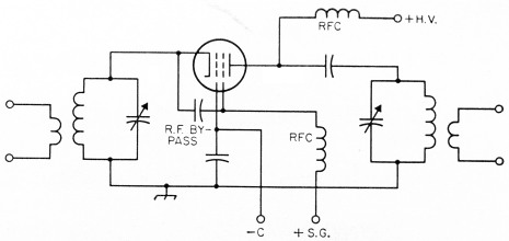
Fig. 2. Grounded-grid circuit in which the screen grid acts as an accelerator of electrons but does not otherwise take part in the amplification process. This corresponds to the part played by the screen in normal grounded-cathode operation, but when connected in this way the No. 2 grid does not act as a shield between the input and output circuits.
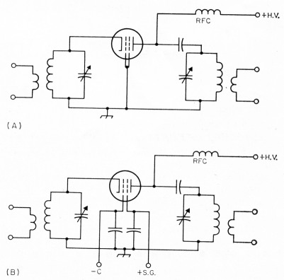
Fig. 3. Triode operation of screen-grid tubes in grounded grid circuits. In A the control and screen grids are connected together to operate as a high-µ control grid. In B, both grids are driven (with respect to cathode) by the same r.f. voltage but are operated with their normal d.c. bias voltages.
The same principles can be used in either case, but no operating characteristics are available from the tube manufacturers covering either type of connection. This is unfortunate, since there are more varieties of tetrodes than triodes in common use today. A tetrode in the circuit of Fig. 3B will allow feeding through comparatively large amounts of power from the driver, if that is a desirable consideration, as compared with the high-is connection, and usually with less grid loss. But in order to make computations similar to those above it would be necessary to have tube data covering simultaneous swinging of the control grid and screen at r.f. while using negative bias on the control grid and positive bias on the screen. It is well-nigh impossible to extrar the necessary information from currently-pulr lished tube characteristics and curves. A meagre amount of operating data has accumulated, all based on amateur experience with particukr amplifiers, but practically none of it is quantita tive in the sense that it can be used for design purposes.