Painless "Q-less" L networks
Easy calculations for impedance matching.
Don't let the graph on this page scare you. By using it, impedance-matching problems are reduced to simple arithmetic.
The L network is a handy gadget for matching two unequal resistances.(1) This presentation shows you an almost painless method of knowing how big to make what if you happen to be needing one.
Furthermore, in spite of what George said, you and I will not even mention Q in the process. That must make it "Q-less"! (I'm just kiddin'.)
To design an L net, let Fig. 1 do most of your work. That picture presents curves which allow obtaining either arm of an L network in terms (a) of the other arm or (b) of either of the resistances being matched.
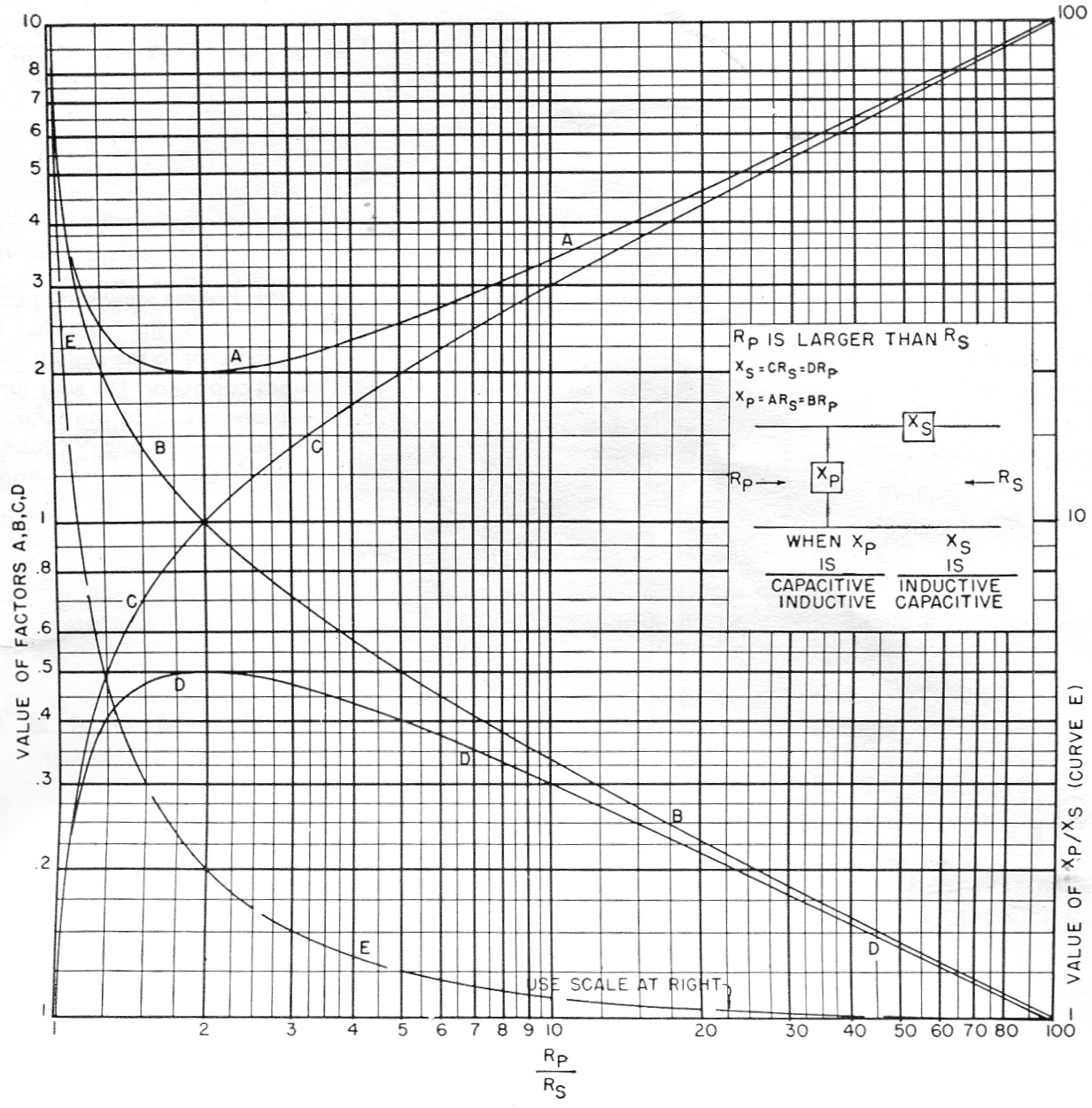
Fig. 1. Factors for obtaining series and shunt reactances for L nets to match resistances haying ratios (Rp/Rs) from 1 to 100.
Let me hasten to say that the information of Fig. 1 is a different way of reaching the same answers as would be attained using the roads followed in the Grammer articles. Fig. 1 does go a little farther, however, by giving two choices for obtaining the series and shunt arms.
Fig. 1 also handles the situation where you have a network in hand and wonder what it's good for. Just find the ratio of Xp to Xs and enter Fig. 1 on Curve E. It will reveal the Rp/Rs for which that particular net works. Curves A, B, C, D will then allow finding Rp and Rs.
To step up impedance, the input voltage is connected across Xp; to step down impedance, the input voltage is connected across the opposite end of the network. As Fig. 1 notes, if Xs is capacitive, Xp must be inductive and vice versa.
Example: Suppose you measured the input impedance to your loaded vertical antenna as 15 ohm and wanted to match it to a 75 ohm feed-line.
![]()
For this value of Rp/Rs, fig. 1 shows that D = 0,4, B = 0.5, C = 2 and A = 2.5.
Using the formulas shown in the box of Fig. 1, Xs = 2 × 15 = 0.4 × 75 = 30 ohm. Xp = 2.5 × 15 = 0.5 × 75 = 37.5 ohm.
As a check, Curve E shows that Xp/XS should be 1.25. Then,
![]()
The same network could be used to step a 75 ohm load down to 15 ohm by reversing the input and output ends.
Curves A and D, incidentally, reveal these interesting (though probably useless, except for checking) bits of information:
- Xp can never be smaller than twice the smaller resistance being matched.
- Xs can never be larger than half the larger resistance being matched.
- For either Xp or Xs there are two different values of Rp/Rs which call for the same value of shunt or series reactance; e.g., Xp = 2.5 Rs at Rp/Rs = 1.25 and at Rp/Rs = 5.
Fig. 1 allows you to double check by using two different methods to reach the same answer. It aids in visualizing the relative sizes (in ohms) of the elements, and lets you make a final check on accuracy by looking at the ratio of Xp to Xs.
May you find it helpful!
Notes
- Grammer, "Simplified design of impedance-matching networks" (Part 1 - "Basic principles and the L network"), QST, March, 1957.
R.K. Ghormley, W0UPH.