The impromtu ground plane
Three-band vertical for a few bucks.
As the title suggests, this ground plane for 20, 15, and 10 was intended originally only as an expedient when a multiband antenna of some sort was needed in a hurry. But it has worked so well that it will probably be some time before it is replaced. It was in operation within a few hours after it was started. By including the coax feedline as part of the radiator, it has also done a creditable job on 40 and 80 too.
It must be admitted at the outset that the subtitle above is a little misleading. Like the 1 mA meter so many article writers seem to be able to find on a dusty shelf when their gadget needs one, it assumes that you can find at least one fair-size tree in your junk box. The ham with a wooded lot, where clear space for a horizontal at reasonable height and running in the right direction may be hard to find, will be the one most likely to take advantage of a contraption of this sort. Trees, when they are in the right spots, provide height at low cost. But horizontal antennas swung between trees at any appreciable height have a habit of coming down an hour after the contest starts. This vertical has a chance of staying put, even in rough weather.
The multiband part is an outgrowth of the 4 parallel-dipole system which vies in popularity with the trap multiband dipole among those poor souls who still think in terms of simple antennas. The idea was first suggested in print by K5AYJ.(1) Quarter-wave radiators, one for each of the three bands (20, 15 and 10 in this case) are simply tied together at the base. The ground-plane radials are similarly cut and joined and the combination is fed with a single 50 ohm coax line.
Construction
The construction is shown in Fig. 1. The support for the three radiators is a 16-foot 2 × 2 of fir. The radiators are lengths of 300-ohm TV Twin-Lead (no special significance, of course, except that it is insulated and can he picked up at the corner TV store on a Saturday afternoon) with the two conductors connected in parallel. They are mounted on screw-type TV stand-off insulators. Use the longest size (7% inches) so that those on the sides can be bent forward to occupy less space and avoid interference from branches. Since the 20-meter radiator is a little longer than the stick, the top insulator is screwed into the end of the 2 × 2 instead of the side. Mount the 20-meter radiator on the side of the 2 × 2 opposite to the side that will be against the tree trunk. The choice of sides for the other two radiators will depend on which gives the best clearance from branches. To make sure that the line doesn't slip in the insulators, pinch the retaining rings of the insulators with a pair of gas pliers after the line has been threaded through, and wind a wad of plastic tape over the top end of each radiator, just above the top insulator: The bottom ends of all radiator wires are soldered together and this joint, of course, goes to the center conductor of the coax line. Small porcelain stand-offs at the bottom of the 2 × 2 make convenient terminals for the coax connections.
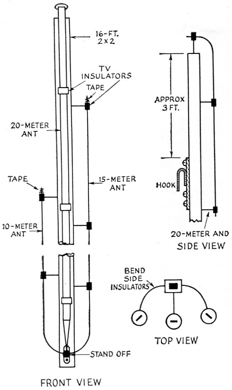
Fig. 1. Sketch showing construction of the "Impromptu" three-band ground-plane antenna. Radiator elements are of 300 ohm Twin-Lead on TV stand-off insulators, fastened to a 16 foot 2 × 2. Radiator and radial lengths are 16 feet 6 inches for 20 meters, 11 feet 2 inches for 15, and 8 feet 3 inches for 10 meters.
The heart of the construction is the simple, but essential hook fastened about 3 feet from the top of the pole. This is snagged over a crotch in the tree and, among other things, permits getting the stick higher in the tree than it might be safe to climb. You have to climb only as far as the bottom end of the pole. Suspended by the hook, there is little more strain on the 2 × 2 than there might be on a candy cane hanging on a Christmas tree. This antenna has out-ridden some of the stiffest gales of the year, even though it is mounted in the uppermost part of the tree where movement is a matter of feet in a strong wind.
While looking around in the basement for a likely prospect to serve as a hook, I spotted an old plasterer's trowel - the kind that has a wood handle running parallel to a rectangular sheet-metal plate. Knocking off the wood handle left an almost ideal metal hook complete with a mounting plate that could be drilled for 1%2-inch No. 10 round-head wood screws. These trowels can be found at almost any hardware store and cost about 50 cents. You may dig up something even better or handier.
Most trees have one side that is relatively free of branches. You can find the best side by sighting up along the trunk from the ground. While you're doing this try to spot a sharp crotch up near the top of the tree with a branch diameter of about an inch.
Mounting
The antenna assembly is not very heavy and it was not too difficult for one man, even on a windy day, to hoist the 2 × 2, by rope, to the top of a 25 foot ladder (in lieu of lower branches), and then slide it upward along the trunk of the tree until the hook fell into place in the crotch above. Keep the bottom of the stick out away from the trunk as far as you can, so that the stick will lean against the tree as it is being pushed up. The bottom end of the pole should have only a loose binding to the tree trunk so that it can have restricted movement in all directions.
Radials
Four-conductor poly-insulated TV-rotator control wire was used for the radials, of which there are four spaced approximately 90 degrees. The individual conductors of each radial were cut to lengths corresponding to the lengths of the radiators, two conductors in parallel being used for the 20-meter radials since these are the ones that take the strain. The excess wire left after cutting the shorter 15- and 10 meter radials was peeled off. At the antenna end, all radials are connected together and to the shield of the coax feed line.
On a wooded lot, there will usually be other trees that can be used as supports for the radials even though they may not be spaced ideally, and the house, garage or short poles can be pressed into service. It doesn't seem to be too important that the radials run horizontally. There was no difference that could be noticed when the radials were lifted from a temporary angle of about.45 degrees up to horizontal.
There will, of course, be some movement of the tree where the radials are anchored just below the antenna, and still more movement of the radials if other trees are used as supports. Extensions of awning cord were used at the ends the tree to the base of the antenna (in this case, about 30 feet above ground). A turn of the coax around a branch, secured by plastic tape, takes the strain off the connection to the antenna. Leave a little slack in the coax to allow for movement of the bottom of the pole.
The antenna had its baptism in the QRM of the October CD contest which started a couple of hours after the job was finished. With 250 watts input on c.w., it was seldom necessary to call a station more than once on any of the three bands. An unexpected bonus paid off when the two sides of the coax were tied together and the system worked against a waterpipe ground on 40 and 80. The length of the coax (about 50 ft.) was such that the feedpoint impedance was within the range of the pi network in the transmitter. (The system resembles an overgrown mobile antenna with the radials as a capacitive hat.) This arrangement also worked very well with 40-meter contacts with K116 and KL7 and several West Coast contacts on 80. In the SS contest that followed, over 500 contacts in 72 sections were made with 150 watts input. DX worked within the past month with 250 watts includes BV1US, BV1USB, CR9AH, FF8AC/GN, FO8AW, HS1C, JAs 1AA, 1BC, 1KM, 1PS, IVE, 2JW, 3SJ, 3TA, 3171, 411M, 4JQ, 6AP. 8AA, 8AH, 9AA, OFZ; JT1YL, KA2CB, KA2KM, KC4USK, KG6NAA, KR6CA, KR6DY, KW6CU, KX6BP, OR4VN, SM5WN/LA/P, UL7FA, UL7KAA, UM8DB, UO5PK, UA9s AK, CC, DM. DR, OB, SB, VB, KCA, KCK, KMA, KQA; UAOs CF, CI, CN, FC, FE, JB, KJA, KOC, KSA, KUV; VK9AD, VS6AE, VS9AC, VU2AJ, ZD2GWS, ZD7SA, ZK2AD, ZP6FA and 4X4CJ on 20; DU7SV, ET2VB, JAs lEC, 3BP, 5AI; KA2BE, KA2RB, KM6BL, KR6AK, OR4VN, SVOWP, UA6UF, VQ4CC, VS9AS, VS9AQ, and ZE5JE on 15; JAs 1BQR, lEC, 1VX, 2YT, 3ALQ, 3BN, 3GM, 31S, 7AD; KA8RA, KJ6BV, ZK1BS on 10; and couple dozen Europeans and 4X4KK on 40. Which goes to show that a lot can still be done with less than the optimum.
Notes
Donald Mix," W1TS