Simple phone monitor
Continuous check for A.M. stations.
K1CLD finds that even in these days of oscilloscopes, the simple monitor that has been around for years can tell you a lot about your phone signals. Furthermore, you can hear the trouble and don't have to depend on an interpretation of a pattern.
Some months ago, shortly after I had received my license and had got on the air, I had a most disquieting report about my signal. I was on 20 phone and the other chap said, "Sorry, Bill, missed some of that last transmission funny noise kept coming and going - sounds like telephone dial tone - covers you right up." So I signed with him and tried to figure out what was wrong. The trouble didn't take long to find or to fix. It was a loose connection on the shield braid in the mike cable. But it made me realize that I should be able to monitor my signal at all times and not be guilty of putting any such racket on the air again.
Well, I had a scope gathering dust on the shelf. So I dug it out, made up a coupling circuit, and set it up so that I could check my modulation at any time while I was transmitting. I learned several things from this, to wit:
- It did all the Handbook said it would in regard to checking modulation percentage.
- It is not easy to watch it all the time.
- It makes a wonderful impression on visitors to the shack.
- It still didn't tell me what I sounded like.
I tried to use the station receiver as a monitor, but without much success. The receiver overloaded and was not convenient at best. Therefore I decided that some separate unit would have to be built.
The only phone monitor circuit I could find was in a tube manual, and it seemed unnecessarily complex (meaning parts not in my junk box). So, to make a long story short, I adapted a circuit that I found in a field-strength indicator in the 1956 ARRL Antenna Book. It is very simple, as the circuit of Fig. 1 shows. It uses no tuned circuite and works very well with my 100 watt of r.f. on 10 through 160 meter. Also, by cutting out the 0.1 µF blocking capacitor, the d.c. component may be used to power a transistor c.w. monitor, the volume control in this case becoming a tone control.
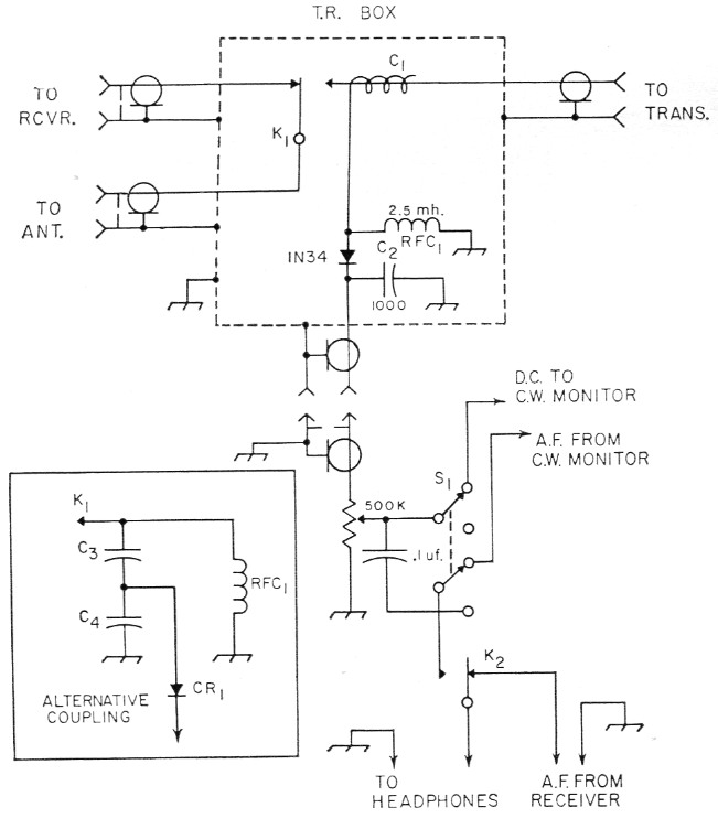
Fig. 1. Circuit of K1CLD's monitoring system.
| C1 | See text. |
| C2 | Disk ceramic or feedthrough (see text). |
| C3 | 10 pF mica (see text). |
| C4 | 100 pF mica (see text). |
| CR1 | See text. |
| K1 | Antenna relay. |
| K2 | S.p.d.t. relay, coil to operate from same source as coil of K1. Windings of K1 and K2 should be connected in parallel. |
| RFC1 | 2.5 mH r.f. choke. |
| S1 | D.p.d.t. toggle switch. |
At K1CLD I use a home-built t.r. relay. This consists of a surplus relay mounted in a shield box. C1, RFC1, the 1N34 and C2 are mounted in this box. The volume control and other components are placed near the operating position. There is nothing critical about anything in this circuit; you could even place the detector section in the transmitter cabinet. However, if you do this, be sure to bypass the output for TVI in the usual manner (a feed-through type capacitor for C2 should do the job). Or, you could use a short pick-up antenna and not connect the monitor to the transmission line at all.(1)
The value of C1 will depend on the power of the transmitter. Here, with 100 watt of r.f., C1 consists of four turns of heavily insulated hookup wire wound around the "live" conductor in the t.r. switch, the capacitance being, I imagine, in the neighborhood of 5 pF. Adjust its value for a d.c. output (measured with a v.t.v.m. across CO of about 10 volt. With this voltage (input frequency 14 Mc.), adequate audio volume is obtained on all bands (using high-impedance phones). As an alternative, the capacitive voltage divider circuit might be used. (See Fig. 1.) But in any case be sure that C1 will withstand the maximum voltage appearing at the transmitter output. With the voltage divider, a crystal diode with a higher voltage rating than the 1N34 would probably be advisable.(2)
In operation, when you switch to "Transmit," relay K2 operates simultaneously with the t.r. relay, removing the phones from the receiver output and connecting them to the monitor. Switching to "Receive" releases K2 and restores the circuit to normal. The relay, K2, is not really necessary; a toggle switch could, be used, but would not be anywhere near as convenient.
It is obvious that it would be impractical to try to use a speaker with this monitor. There is not enough output to drive a speaker, and if there were, feedback would result. However, if you really must use a speaker - can't get on without it - you can still use phones connected to the monitor and listen now and then with one ear!
Once having installed this little unit I would feel quite lost without it. It tells me what my signal really sounds like - something the scope won't do - and if anything is wrong with my audio, I am the first to know it. I do not wish you to think that I am advocating this a: a substitute for a scope for modulation checking - far from it - for it is not. It does, though, take over where the scope leaves off. It will reveal hum and distortion of too low a level to make a. significant showing on the scope screen. Also, with my transmitter, I find it of help in tuning up as, in dipping the final, I notice that the audio quality is better when I tune very slightly to one side or the other of exact resonance.(3) And last, but not least, it enabled me to track down an elusive low-level bit of feedback I had on 10 meters!
I trust that anyone who duplicates this unit will find it as helpful as I have.
Notes
- Since diodes rectifying r.f. generate harmonics, this system may cause TVI through radiation from the pickup wire. - Ed.
- By proper adjustment of the voltage-divider capacitances C3 and C4, this should not be necessary. - Ed.
- This may be the result of regeneration in the final, or an adjustment that brings the screen voltage into the optimum region. - Ed.
William R. Deal, K1CLD.