Surplus-crystal high-frequency filters
Selectivity at low cost.
Using the methods and circuits outlined here, the problem of making a usable high-frequency (i.e., in the 4 to 7 Mc range) crystal filter doesn't sound too tough, even with limited test equipment. If you've been interested in some of the newer transmitting and receiving techniques using filters in this range, here's a way to give them a whirl without a large investment.
After all the recent QST articles on uses for high-frequency crystal filters, I've really been coveting one for a mobile s.s.b. transceiver I'm planning. The commercial price tags on filters being what they are, I decided it would have to be built from surplus crystals, or not at all. Having, during the earlier days of s.s.b., suffered with a low-frequency crystal filter (typical report was, "Gee, your voice sounds funny"), I decided to do a little reading before dragging out the soldering iron this time.
A recent article by Kosowsky(1) boils a lot of "long-hair" literature on crystal-lattice theory into a fairly simple and understandable form. One of the most interesting points to me was the fact that the crystal filter designer considers the narrow-band high-frequency crystal filter for s.s.b. to be the "easy" design - the problem getting much more exotic for the wide-band high-frequency filter. Since my buddy, W3HEC, was already tackling the tough problem of making a good low-frequency filter with the FT-241 crystals, I took the easy way out and tried my hand with the high-frequency unit.
Some Background
If you're planning to try your hand at it, it will help if you grab a few fundamental concepts on crystal lattice filters first. The properties of the crystal itself are pretty well known, the approximate equivalent circuit being shown in Fig. 1 and the change of reactance or impedance being shown in Fig. 2. The crystal has two resonances very close together, L and C being in series resonance at f~, and L, C and Co being parallel resonant at fi,. These resonances have been given names by the network theory boys, the series resonance being called a "zero" of impedance (for obvious reasons) and the parallel resonance being called a "pole" of impedance. The symbols used for these are shown on Fig. 2. These poles and zeroes are mighty convenient little symbols for handling networks, the most convenient part being the fact that if you have a circuit with several poles and zeroes, you can often manipulate the circuit values so as to get some of the zeroes each to cancel out a pole. Hence, a circuit with a multitude of resonances (or poles and zeroes) can be arranged to have its response equivalent to only a few resonances.
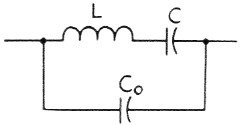
Fig. 1. The equivalent circuit of a crystal. L and C are the electrical equivalents of mechanical constants of the crystal, while Co is the shunting capacitance of the electrodes and holder.
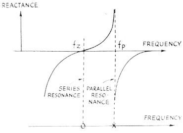
Fig. 2. Reactance characteristics of a crystal. The series-resonant frequency, fs, is that of L and C (Fig. 1) in series; the parallel-resonant frequency, fp, is the resonant frequency of the parallel circuit formed by L and C in one branch and Co in the other.
The universal crystal filter is a lattice circuit. The lattice is usually developed in full "four-arm" form (i.e., as a bridge circuit) and then the equivalence of the half-lattice is proved. The reader is referred to Kosowsky's article and its bibliography for the full treatment on this. We will settle for a few statements on crystal lattice filters which have been adequately proven by others. Consider the simple one-section half lattice shown in Fig. 3. The first important point to consider is that the only way in which the lattice can give a high insertion loss between input and output is for the impedances of A and B to be about equal, so that the voltage at their common connection (point 0) is equal to the voltage at the coil center tap. Our crystals will meet this requirement pretty well if they have the same holder capacitance, so the primary problem is to build the coil so that the voltage from Terminals 1 to 2 is exactly the same as the voltage from 3 and 4. The method for realizing this will be discussed a little later.
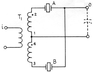
Fig. 3. The half-lattice crystal filter. Crystals A and B should be chosen so that the parallel-resonant frequency of one is the same as the series-resonant frequency of the other. Very tight coupling between the two halves of the secondary of T1, is required for optimum results.
Crystals A and B are chosen to be different in frequency for the half lattice. Thus it is obvious that if we are at a zero (series resonant) frequency of, say, crystal A, the impedance balance of A and B is spoiled and there is a voltage showing up between point O and the center of the coil. This will also occur at the pole (parallel resonant) frequency of crystal A. The same can be said for crystal B, only the unbalance is in the opposite direction. This leads us directly into the statement that the pass band of the crystal filter will be as wide as the spacing of all the poles and zeroes. This says nothing about the ripple or variation in transmission in the pass band, however, and if A and B are far apart the ripple or dip may be tremendous. Here's where the network theory boys' trick of pairing off poles and zeroes comes in handy. A little study with Fig. 2 of the way in which the impedance change around a zero differs from that around a pole will give an idea how the lattice crystals can be arranged to give a flat pass band. Fig. 4 shows the desired arrangement. The series-resonant frequency of crystal B is arranged to coincide with the parallel-resonant frequency of crystal A. This will theoretically give a perfectly flat pass band from the zero of crystal A to the pole of crystal B.
Our problem is now resolved down to determining the pole-zero spacing for the available crystals. The surplus FT-243 crystals in the 5-Me. range (this choice of frequency was Obviously based on the excellent results being obtained with the popular HT-32 transmitter) have a measured spacing of about 2.2 kc. between their series- and parallel-resonant frequencies. Thus, two of them spaced 2.2 kc. apart in frequency are theoretically capable of giving a 4.4 kc. bandwidth. Practically, it is very difficult to get quite this much bandwidth.
If we examine the effects that the external coupling circuitry has on the pole-zero spacing, it can be shown that both an increase and a decrease in the spacing can be accomplished, by shunting inductance or capacitance, respectively, across the crystal. The most familiar example of this to most of us is in puffing a crystal oscillator's frequency by shunting a capacitor across the crystal. This technique, you will remember, only works where the crystal is being used in its parallel-resonant mode. Referring back to Fig. 1, it is easily seen that a parallel capacitor makes Co larger and lowers the parallel-resonant frequency (pole). It will not affect the series-resonant frequency (zero), so the effect of the parallel capacitor is to move the pole closer to the zero. Similarly, it can be shown that an inductance shunted around the crystal will push the pole away from the zero; unfortunately, however, this also introduces a second parallel-resonant frequency. Even the network theory boys begin to sweat a little when they begin to manipulate this many poles and zeroes in a lattice circuit, so we hams had better avoid the complications, and shy away from trying to add tuned inductors on the input and output of the filter. If we are forced to use an inductor, we will make its inductance large enough to avoid its resonating with Co anywhere near the desired pass band.
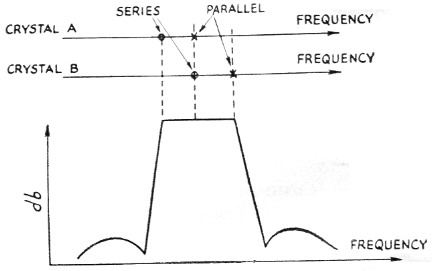
Fig. 4. The theoretical attenuation-vs.-frequency curve of a half-lattice filter shows a flat pass band between the lower series-resonant frequency and higher parallel-resonant frequency of the pair of crystals.
Preliminary Measurements
Now that we have some ideas as to how crystal filters work, we will get more specific and look at the procedure by which one may be evolved. To measure the spacing between the series- and parallel-resonant frequencies, we must be careful to avoid having the test circuit put shunt capacitance across the crystal and give erroneous results. The circuit in Fig. 5 was used by the writer. To eliminate the extra shunt capacitance that a socket would add, the crystal holders were soldered directly into the circuit. The signal generator can be most any kind, so long as it has a slow tuning rate - I used one of the Command transmitters. The measurement detector can be a scope, a v.t.v.m. (with r.f. probe), or the station receiver. The low resistapce R2, across it should swamp out any small amount of input capacitance it might have. If a receiver is used, a 1K or 2K resistor should probably be put in series with its input to isolate the crystal from the receiver front-end tuned circuits. The series- and parallel-resonant frequencies are, of course, at the peak and null of the signal across R2. Any decent communications receiver will measure the frequency difference; best accuracy is obtained by measuring the harmonics of the generator with the receiver in the sharp crystal-filter position.(2)
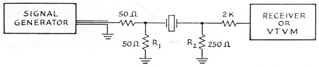
Fig. 5. Setup for measuring the series-and parallel-resonant frequencies (or pole-zero spacing) of a crystal.
Initial measurements of the two 5645 kc crystals I had showed a pole-to-zero spacing of 2.2 kc. on one and 2.4 kc. on the other. Their series-resonant frequencies were about 560 cycles apart. I decided to try these out first to get a bearing on the problem.
As indicated earlier, the push-pull coil must have very tight coupling between its two secondaries and should be chosen with a high enough inductance to avoid resonance with the crystal shunt capacitance near the pass band. I used a ¾ inch ferrite toroid (origin and properties unknown) with the secondaries wound bifilar. The bifilar winding is illustrated in Fig. 6. The enclosed LS series coils made by CTC probably would work just as well. (It would probably be very difficult to get tight enough coupling with air-wound coils, however.) I arbitrarily made each half of the secondary coil with an inductance of 50 microhenrys; this required 25 bifilar turns, or 50 turns total. The exact inductance is not at all crucial - the important thing is the tight coupling.
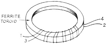
Fig. 6. Bifilar winding on a toroidal core.
Experimental results
A filter was constructed with the circuit shown in Fig. 3. It was fed from a low impedance and its output was fed into a 6AK5 mixer grid, the mixer grid effectively shunting some capacitance across the crystals. This mixer was used to beat the filter output signal into a range which was covered by my receiver (a 75A-3) so the receiver could be used for both db. and frequency measurements. The initial response was as shown by curve "A" in Fig. 7. A 10K resistor was then added to terminate the filter and the response squared up (as shown by curve "B") to give a passable 1 kc high-frequency filter.
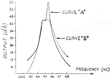
Fig. 7. Measured attenuation curves of a half-lattice filter using two nominal 5645 kc crystals having series-resonant frequencies separated by 560 cycles. A-without resistance termination; B-with 10,000 ohm terminating resistor. In taking the data for these curves and those shown in Figs. 8, 9 and 11, the attenuation was based on the manufacturer's calibration of the receiver used in the tests.
This was sufficiently encouraging, so I dug out the ammonium bifluoride(3) etching bath from its hiding place and moved the upper-frequency crystal to a frequency 1500 cycles above the lower frequency (W2IHW's technique for etching crystals is really simple).
The initial results with this were anything but encouraging. Curve "C" in Fig. 8 illustrates the results. It was obvious that the capacitance across the lattice output had shoved the poles too close to the zeroes, or else the 500 kΩ terminating resistor was improper. I tried tuning the capacitance out with a slug-tuned coil and got all kinds of interesting results (curve "D" in Fig. 8 is typical), none of them usable. When I terminated the filter with lower values of resistance, however, the results improved markedly. With just the right resistor, 1.5K in this case, the pass band was flat over a reasonable width. Curve : "E" in Fig. 9 shows the final results. The bandwidth is just barely great enough for phone use.
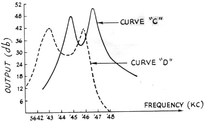
Fig. 8. Attenuation curves of half-lattice filter with crystals of the same nominal frequency as in Fig. 7, but with 1.5 kc separation. C-with 0.5 megohm terminating resistor; D-shunt coil added across the output to resonate with capacitance present at that point.
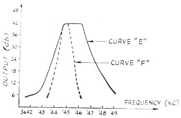
Fig. 9. E-half-lattice filter using same crystals as in Fig. 8, with 1500 ohm terminating resistor. Fusing two nominal 5645-kc. crystals separated 300 cycles, with 3900 ohm terminating resistor.
Since I had one other 5645 kc crystal which was 300 cycles from one of the original crystals, I substituted it in and got curve "F" in Fig. 9. This time a 3.9K terminating resistor gave the flattest pass band.
If greater rejection off the skirts is required, there are several ways in which these sections can be cascaded. Crystals of the same frequency can be paralleled on the half-lattice arms, or an isolating tube can be placed between two sections. A simpler technique is to connect them back to back as shown in Fig. 10. This method of connection will minimize spurious off-frequency responses since the probability of getting the spurious responses of crystals A and B to line up with those of crystals A' and B' is pretty small. The coil, L1, is again wound bifilar and R1 and R2 are chosen experimentally for the best pass band. The crystals should be matched as closely as you can read their frequency - this is pretty easy with the etching technique. Fig. 11 shows the response I got from four 7300 kc crystals, connected like Fig. 10 (crystals A and A' were L5 kc. higher than B and B'). The same bifilar coil was used. Incidentally, I got a peep inside one of the 9 Mc commercial s.s.b. filters recently and they used this circuit. Their filter used an L8-9 coil (C.T.C. Corp.) for L1.
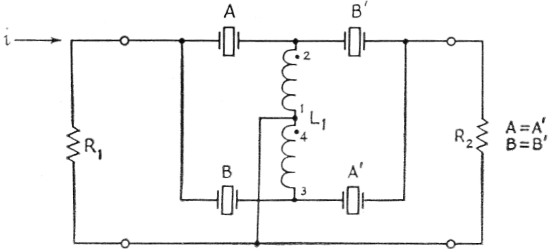
Fig. 10. Half-lattice filters cascaded in a back-to-back arrangement. The theoretical curve of such o filter has increased skirt selectivity and fewer spurious responses, as compared with a simple half lattice, but the same pass band as the simple circuit.
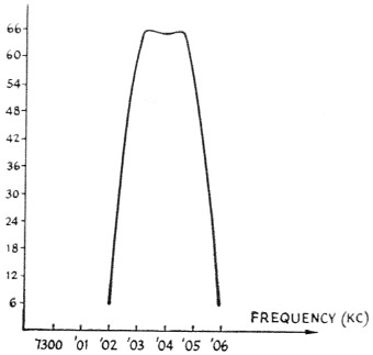
Fig. 11. Attenuation curve of filter using four nominal 7300 kc crystals, pairs separated 1,5 kc, in the circuit of Fig. 1.
I measured the spacing between series and parallel resonance of a few of the other surplus crystals that were lying around and got the following results:
| Crystal Frequency | Type | Pole-Zero spacing |
|---|---|---|
| 8725 kc | FT-243 | 2.7 kc. |
| 7250 kc | FT-243 | 2.3 kc. |
| 7380 kc | Plated-surplus | 5 kc. |
| 7010 kc | Plated-surplus | 6 kc. |
| 8900 kc | Plated-harmonic cut | 20 kc. |
Obviously, the plated crystals will give wider-band filters.
If you're interested in an asymmetrical filter which has a gradual fall-off on one side, then the circuit shown in Fig. 12 can be used. Here both the crystals are on exactly the same frequency. The coils are again bifilar and C is tuned to give the desired pass band. The potential bandwith here is only half that obtained with the half-lattice. It should work nicely with the plated crystals, however.
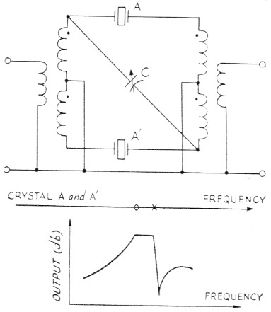
Fig. 12. An asymmetrical filter and theoretical attenuation curve.
I hope this will encourage some of you fellows to try your hand at building filters. I only have a handful of crystals and have only spent a couple of weeks playing with them, so I haven't had an opportunity to try all the circuits. By the way, if any of you find out what's in the HT-32 crystal filters, drop me a line.
Notes
- Kosowsky, "High frequency crystal filter design techniques and applications," Proceedings of the IRE, Feb., 1958.
- I.e., after adjusting the generator to the series-resonant frequency, let the generator alone and shift the receiver to some higher range where a generator harmonic can be heard and its frequency measured. Then shift back to the fundamental frequency, adjust the generator to the parallel-resonant frequency, shift the receiver again and then measure the generator harmonic adjacent to the first one. The frequency separation between the crystals is of course equal to the frequency difference between the harmonics divided by the order of the harmonic. This method usually will give improved accuracy only if the receiver calibration can be read to the same accuracy - e.g., 1 kc per dial division - on the harmonic range as on the fundamental. - Editor.
- Newland, "A safe method for etching crystals," QST, Jan., 1958.
Benjamin H. Vester, W3TLN.