The electronic eyeball
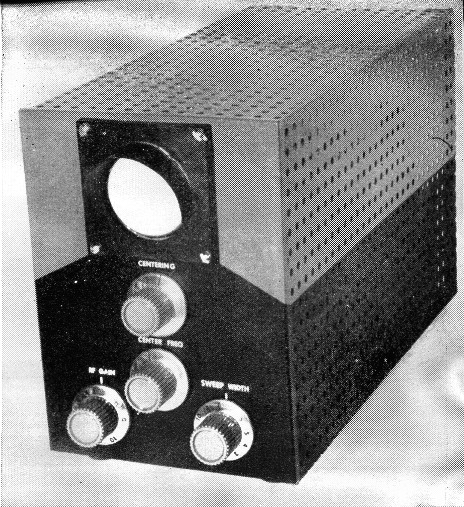
Complete panoramic adapter in one package.
The "electronic eyeball" is a panoramic adapter using a 2-inch oscilloscope.
For a number of years a smart small core of hams has enjoyed the benefits of "panoramic reception," an electronic representation of the portion of the spectrum to which the receiver is tuned. If you would like to be "one of the boys," this article is for you.
For some time I had been collecting parts for a home-built receiver project. This receiver was to have included a panoramic display as one of its features. Before I had accumulated all of the parts there became available on the market several amateur communication receivers that meet my requirements. The only thing lacking was the panoramic display. I dropped my plans for a home-built receiver in favor of a commercial unit and proceeded to build the panoramic display for the new receiver.
The unit described here is an adaptation of the "Snooper" built by W7H1 A.(1) It consists of a low-frequency superheterodyne receiver whose local oscillator is frequency-modulated by the same sweep generator that drives the horizontal sweep circuit of the display indicator (2-inch oscilloscope). As the local oscillator is swept back and forth across the band the received signals are detected and fed to the vertical circuit of the display indicator. Each signal appears as a vertical pip above the horizontal base line, as shown in Fig. 1.
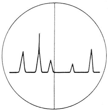
Fig. 1. Typical display of a panoramic adapter ("electronic eyeball"). Each "pip" represents a signal on the band; a strong signal will rise higher than a weak one. The pip corresponding with the center vertical line represents the signal to which the receiver is tuned. As the receiver is tuned across the band, the pips move sideways.
If the deviation is decreased, the presentation is expanded until only one pip will occupy the entire screen.
This device is an aid to more efficient operation, like other auxiliary equipment found in the ham shack (Q5-er, Q Multiplier, secondary standard, etc.). Band conditions on and around the received frequency may be observed. Also, some of the characteristics of the received signal can be determined, such as splatter, carrier shift, relative carrier strength, and spurious signals. The netting (zero beat) of several stations on one frequency is made much easier.
The circuit
Looking at the schematic diagram of Fig. 2 we find many familiar circuits. The 6AB4 detector uses the infinite-impedance circuit described in Chapter 5 of The Radio Amateur's Handbook, 1957 edition. The 6AK5 reactance modulator circuit is the same one that is used in many amateur narrow-band frequency-modulated transmitters; it is described in Chapter 11 of the same handbook. A voltage-doubling circuit provides the negative voltage for the 2AP1 indicator tube. The 12AX7 serves as a sawtooth generator and amplifier to drive the reactance modulator and the horizontal plates of the indicator tube.
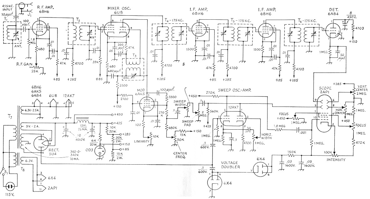
Fig. 2. Circuit diagram of the panoramic adapter. Unless otherwise indicated, capacitances are in µF, resistances are in ohm, resistors are ½ watt. Potentiometers are carbon, linear taper.
| J1 | Phono jack. |
| S1 | Switch on r.f. gain control. |
| T1,T2,T3 | From BC-453 receiver; see text. Capacitors are 130 pF compression trimmers (El Menco 302). |
| T4 | 175 kc input i.f, transformer (Merit BC-300 or Miller 012-K1). |
| T5 | 175 kc interstage i.f. transformer (Merit BC-301 or Miller 01 2-K2). |
| T6 | 175 kc output i.f. transformer (Merit BC-303 or Miller 01 2-K4). |
| T7 | 680 V c.t. at 70 mA, 6.3 V, 5 V (Stancor PM-8408). |
| T8 | 6.3 V 1.2 aA filament transformer (Stancor P-61 34). |
The power switch is mounted on the r.f. gain control. The 100K intensity control adjusts the brightness of the display; it is set at mid-rotation for initial adjustment. Two focus controls are interacting and control the focus of the horizontal base line. The horizontal centering control on the front panel, and the vertical centering control on the vertically-mounted indicator tube bracket, control the position of the display. A horizontal width control adjusts the width of the base line. The sweep pad control, located on the side of the chassis, is a rough adjustment of the amount of radio-frequency spectrum that is to be viewed, and the sweep width control located on the front panel is a fine adjustment of the same function. Also on the front panel, the center frequency control enables the operator to center the received signal on the base line. A linearity control, located on the side of the chassis, adjusts the linearity of the sweep of the local oscillator and interacts with the center frequency control.
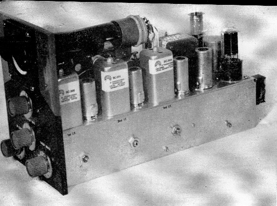
A view under the chassis shows the mica-compression trimmers used to tune the r.f., mixer and oscillator circuits.
Construction
Fig. 3 shows the layout of the major components. To reduce the crowding of components inside the chassis, the filter choke and the heater transformer are mounted on the outside back apron. The hood over the display indicator was made from a scrap piece of tin. The antenna, mixer, and oscillator coils were removed from a surplus BC-453 receiver, although tuned circuits from 455 kc i.f. transformers might be substituted. The cover of the unit was formed from Reynolds perforated aluminum sheet.
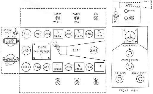
Fig. 3. Parts arrangement on the 5 × 13 × 3 inch chassis. The front panel measures 6 by 8 inches.
Many of the new amateur communications receivers are of the dual conversion type and use a first conversion frequency around 2 Mc. This unit can be made to work at 2 Mc. by substituting broadcast-band receiver coils for the low-frequency antenna, mixer, and oscillator coils. For example, these could be Miller Type 44-A antenna, Miller Type 44-RF mixer, and Miller Type 44-0 oscillator coils.
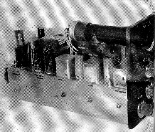
Side views of the panoramic adapter show how the controls have been brought out on both sides of the chassis; note also the controls on the panel under the scope tube.
Adjustment
The initial tuning and adjustment of the unit is similar to the alignment of any superheterodyne receiver, as described in Chapter 5 of The Radio Amateur's Handbook, "Alignment and servicing of superheterodyne receivers." A slight amount of stagger tuning of the r.f. and mixer coils is necessary to achieve a more even response curve.
Connecting the unit to the receiver is simple. Install a phono jack on the rear apron of the receiver chassis. Then connect one end of a short length of RG-59/U coaxial cable to the phono jack. The center conductor of the other end. of the cable is connected to one side of a 3 pF capacitor; the other from the capacitor is connected to the plate of the second converter stage (455 kc) of the receiver. No realignment of the receiver was required. Ground the shield of the coaxial cable at the phono jack only.
Operation
The following information should be of assistance in interpreting the information on the display indicator.
Carrier Shift: This is indicated by a sidewise movement of the pip under modulation.
Modulation: When the carrier is modulated 100 per cent, the height of the pip will double.
Splatter: This will be visible as smaller pips on either side of the received signal, and will appear and disappear with modulation.
Netting: Zero beating your signal with the received signal is accomplished by moving the pip from your v.f.o. to coincide with the received signal.
As described, the unit is capable of displaying signals 20 kc either side of the center frequency of 455 kc.
The writer wishes to thank Mr. Howard Louth, WOSMI, for photographing the equipment.
Notes
Louis I. Hutton, W0RQF.