Adjustable load for calibrating S.W.R. bridges
Here's a simple method of cahbrating over a wide range of s. w.r. values with only one dummy-load resistor, using a variable capacitor to adjust the s.w.r. value at the load. It can be used at any power level for which a resistive dummy that matches the line characteristic impedance is available.
The calibration procedure described below gives true standing-wave-ratio readings with all types of s.w.r. instruments, and is a convenient method to use since only a single dummy load is needed. In brief, the procedure consists of adding reactance (in this case, capacitors) in series with a dummy load of the same resistance as the characteristic impedance of the line with which the s.w.r. bridge is to be used. By thus making the load reactive, it is possible tH obtain various values of s.w.r. The formula for determining the size of series reactance required is:
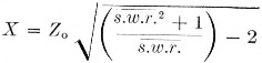
X is the value of reactance in ohms, Zo, is the characteristic impedance of the line and the resistance of the dummy load, usually about 50 or 70 ohms, and s.w.r. is the required s.w.r. The X value can then be converted directly to micromicrofarads (or microhenries, if you happen to have some calibrated coils around) at the frequency of calibration by use of a reactance chart or formula (X = 1/2πfC), as explained in the ARRL Handbook.
The values of series capacitors required for both the 40 meter and 15 meter bands, for various values of s.w.r., are given in Table I, one column for 50 ohm instruments, the other for the 70 ohm variety. To set up each load, simply insert a capacitor of the value listed (or calculated) in series with the dummy load, and connect the combination to the load terminals on the s.w.r. meter. The writer used a 500 pF straight-line-capacitance variable set for the desired capacitance on the basis of percentage of total rotation - i.e., when the capacitor is half closed we have 250 pF, and so on. For values above 500 pF, fixed 10 per cent tolerance capacitors can be connected in parallel with the variable.
If you have several 100 pF fixed capacitors around, you can use them to calibrate an s.w.r. scale instead of setting up the values in Table I. The s.w.r. resulting from series and parallel di combinations of 100 pF capacitors in series with 50 and 70 ohm dummy loads on the 40 meter band (7200 kc) and 15 meter band (21300 kc) are given in Table II.
| Series Capacitance | Standing wave ratio | |
|---|---|---|
| 50 Ohm load | 70 Ohm load | |
| 7 Mc Band (7250 kc.): | ||
| 50 | 80:1 | 40:1 |
| 75 | 37:1 | 19:1 |
| 100 | 21:1 | 11.7:1 |
| 150 | 11:1 | 6.1:1 |
| 200 | 6.8:1 | 4.2:1 |
| 300 | 3.8:1 | 2.7:1 |
| 400 | 2.8:1 | 2.15:1 |
| 600 | 2.1:1 | 1.7:1 |
| 1000 | 1.5:1 | 1.35:1 |
| 21 Mc Band (21,300 kc): | ||
| 25 | 38:1 | 20:1 |
| 50 | 10.8:1 | 6.4:1 |
| 75 | 5.8:1 | 3.7:1 |
| 100 | 4.0:1 | 2.8:1 |
| 150 | 2.6:1 | 2.0:1 |
| 200 | 2.1:1 | 1.7:1 |
| 250 | 1.8:1 | 1.5:1 |
| 300 | 1.6:1 | 1.4:1 |
| 500 | 1.35:1 | 1.25:1 |
| S.W.R. | Reactance (Ohm) required | Capacitance (pF) required, 7200 kc | Capacitance (pF) required, 21,300 kc | |||
|---|---|---|---|---|---|---|
| 50 Ohm load | 70 Ohm load | 50 Ohm load and line | 70 Ohm load an line | 50 Ohm load and line | 70 Ohm load an line | |
| 1.2:1 | 9 | 13 | 2460 | 1760 | 830 | 593 |
| 1.5:1 | 21 | 29 | 1050 | 752 | 356 | 254 |
| 1.8:1 | 30 | 42 | 735 | 525 | 249 | 178 |
| 2.0:1 | 35 | 49 | 630 | 450 | 214 | 153 |
| 2.5:1 | 47 | 66 | 470 | 336 | 159 | 114 |
| 5.0:1 | 90 | 126 | 246 | 176 | 83 | 59 |
| 10.0:1 | 142 | 199 | : 155 | 111 | 53 | 38 |
| 20.0:1 | 210 | 294 | 105 | 75 | 36 | 26 |
| 50.0:1 | 350 | 490 | 63 | 45 | 21 | 15 |
To make up a calibration curve, list the s.w.r. values in a column, and list the meter readings obtained in the "reflected" position beside the corresponding values of s.w.r. (Remember always to adjust the sensitivity potentiometer for a full-scale reading in the "forward" position - if the instrument has such a control - before switching to the "reflected" position and record-. ing the meter reading.) The table can be used by itself, or you can plot the resulting curve on two-cycle log paper. Calculated in this way, the readings should check out against a commercial instrument within 15 per cent.
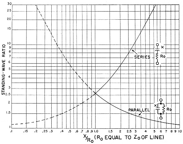
Fig. 1. Values of reactance required to be inserted either in series or parallel with a resistance equal to the characteristic impedance of the line, for obtaining various standing-wave ratios for calibration purposes. Values of reactance read from the chart are "normalized" to the line impedance and must be multiplied by the characteristic impedance of the line to find actual values in ohms. The resistive dummy load, R", must accurately match the line impedance. Reactance values can be converted to capacitance (or inductance, since either may be used) by the usual formulas or with the aid of reactance charts such as are given in the chapter on circuit fundamentals in the Handbook.
Editor's Note: The information above originally was part of the author's article on the MickeyMatch,1 but we thought the idea too good to risk its being "lost" to those who already have s.w.r. bridges, and therefore possibly would have overlooked it in the constructional details of the Mickey-Match. The method can, of course, be used for calibrating any s.w.r.-measuring instrument, at any power level for which a suitable resistive dummy load is available.
The s.w.r. vs. reactance data also can be presented graphically as shown in Fig. 1, and the idea can be usefully extended to include putting the reactance in parallel with the resistive dummy, as is also shown in Fig. 1. These curves, which are normalized to the line characteristic impedance and thus can be applied to any type of line, cross at the value X/Ro = 1, at which value the s.w.r. is 2.6 to 1. Thus (solid curves) s.w.r. values higher than 2.6 to 1 can be secured by putting X in series with Ro, and s.w.r. values lower than 2.6 to 1 can be secured by putting X in parallel with Ro; this is convenient because it means that a single variable capacitor having a minimum value X = Ro at the measurement frequency can be used for the entire practical range of s.w.r. measurements. As a guide, the maximum capacitance required for the low-frequency end of each band is as follows:
| Freq. | 52 Ohm | 75 Ohm |
|---|---|---|
| 3.5 | 874 pF | 605 pF |
| 7 | 437 pF | 303 pF |
| 14 | 218 pF | 151 pF |
| 21 | 145 pF | 101 pF |
| 28 | 109 pF | 76 pF |
| 50 | 61 pF | 42.4 pF |
It should not be necessary, ordinarily, to calibrate a bridge at more than one frequency. Thus any available variable capacitor can be used, if the frequency is selected so that a reactance value numerically equal to the characteristic impedance of the line will be within the adjustment range of the capacitor. If desired, the calibration can be checked at a few points on lower frequencies by using fixed capacitors or combinations of fixed capacitors.
For somewhat higher accuracy than the proportional-rotation method of estimating capacitance described above by the author, the variable capacitor can be calibrated as described in the chapter on measurements in the Handbook, using a standard inductor and grid-dip meter. For most work this is probably an unnecessary refinement, if a straight-line capacitance variable is used and allowance is made for the fact that the capacitance has a minimum value at the "zero" setting.
Notes
Robert C. Bunce, K6QHZ.