Solving your TVI problem
Some suggestions for the novice.
Interference to television reception by amateur transmitters may be divided into distinct categories, each one requiring a different treatment. This discussion of the causes and cures includes details of a simple low-pass filter.
Soon after getting into amateur radio, the newcomer will discover that a subject of general . interest is something called "TVI." You won't find TVI defined in Webster's dictionary. But if it were, the definition might go something like this: "TVI - Garbling of received television signals by interference from undesired signals." These undesired signals have many different sources such as electrical devices with sparking contacts, industrial heating equipment, diathermy, short-wave stations, and many others. But there are only two types of TVI of direct concern to the amateur. First is the type of interference that is caused by spurious signals emanating from his transmitter at the same frequency as that of the television signal. The second type of interference is caused by the legitimate transmitter signal at the operating frequency.
The first is distinctly the amateur's responsibility, since regulations require that the radiated energy from a transmitter be confined to the authorized operating frequency. The second type of interference is a result of deficiencies in the television receiver itself. While it is therefore not a direct responsibility of the amateur, it is not a problem that he can entirely ignore.
Interference from spurious signals
Let's tack a definition on spurious signals so you'll know what they are. Spurious signals resulting from operation of your transmitter are any signals other than your fundamental, the fundamental being the signal you are using for communication. Spurious signals fall into two general categories, harmonics and parasitics. Let's take harmonics first and see how they can cause trouble.
The generation of a signal at a desired operating frequency is invariably accompanied by the generation of other lesser signals at multiples of the fundamental frequency. These multiples are called "harmonics," and when they are radiated they are classed as "spurious" signals. If these spurious signals happen to fall in a TV channel, they may ruin the reception of an otherwise perfect picture. How bad the interference to the TV picture or sound may be will depend on the coma parative strengths of the harmonic and the TV signals. If the TV signal is strong enough, it is possible to have a harmonic in the channel without causing TVI.
In the normal course of events, it would be unusual for a ham to cause TVI by harmonics from an 80-meter transmitter. As you go lower in frequency, the harmonics falling in the TV region decrease in strength. Thinking in terms of the Novice power limit of 75 watts input, it is Unlikely that an 80-meter rig could cause TVI except in extremely weak TV-signal areas. On the other hand, one must be on guard against harmonics from a 40-meter rig and definitely expect them in 15-meter operation.
Before discussing methods of eliminating harmonic interference, we must also consider the problem of parasitic signals that can be radiated and cause TVI. You can expect to have harmonics but parasitics are " odd-ball" signals that may be present when the transmitter is operated. They occur when some stage in a transmitter oscillates at some frequency which may be far removed from the operating frequency - often in the region assigned to television. Such signals are not harmonics of the operating frequency; they are usually generated directly at the interfering frequency. A point that should not be forgotten is that factory-built rigs and kits are just as likely to have parasitics (and harmonics) as homebuilt transmitters. Methods of detecting and eliminating parasitics are given in the Radio Amateur's Handbook and won't be treated in detail here. The important thing to remember is that parasitics can cause TVI.
There is nothing very complicated about curing harmonic radiation. In fact, only a minimum amount of work and expense is required to insure a "clean" transmitter. The first step is to close up the transmitter so that any signals leaving the rig can escape via only one route. This route should be through a coax line to the antenna or antenna coupler.
By closing up the transmitter we are referring to a completely shielding enclosure. Although your transmitter may be housed in a metal cabinet it doesn't necessarily mean that it is shielded. Incomplete shielding is seldom better than no shielding at all, and even factory-assembled rigs may require additional work if they are to be considered r.f. "tight." For example, some transmitters have panels with painted surfaces on the sides that fit into the cabinet, or the panel lip on the cabinet may be painted. In order to obtain good shielding, the paint must be removed so that the panel and cabinet are joined by clean metal-to-metal contacts. Screws holding the panel to the cabinet should be not more than three inches apart. Any spacing of screws greater than this may permit the harmonic energy to leak out. Harmonic energy will escape more easily through a slit-type opening than through a circular or square opening of equivalent area. If the transmitter has a hinged lid, the paint should be removed from around the edge where it joins the cabinet, and as with the panel, the lid should be screwed down. The same shielding techniques should be applied to the rear of the cabinet or any areas where there are large openings.
Ventilation holes in the cabinet should not exceed ¼ inch in diameter. If they are larger than this the harmonic energy will tend to leak out. You can use perforated metal for covering large ventilation holes; the Reynolds "Do-It-Yourself" type of aluminum is excellent for the purpose. Once the rig is completely shielded you can be reasonably sure that the r.f. will be confined to escape routes provided by wires emerging from the enclosure. Techniques for filtering power and key leads are described in the BCI-TVI chapter of the Handbook.
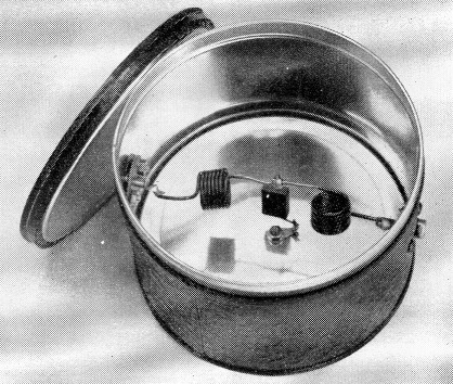
A coffee can is used to house the filter. This type of can makes an excellent shielding enclosure. Phono jacks are mounted on opposite sides of the can and the two coils and the capacitor are mounted inside.
Note that the coils are mounted so that their axes are at right angles to minimize coupling between them. A single ground lug is mounted at the bottom center of the can for the ground connection of C1.
Low-pass filters
This leaves us with only one more problem - that of preventing the harmonics from reaching the antenna through the feed line. The answer is to install a low-pass filter at the transmitter output. A low-pass filter is simply an "electrical gate" that permits your fundamental to reach the antenna but which stops harmonics. The filter is a coil-capacitor combination that is designed to attenuate any signal above a certain "cut-off" frequency. Any signals higher in frequency than the cut-off frequency are attenuated, while the signals below the cut-off frequency are permitted to pass through the filter.
The filter is a simple device and the one described here can be built in an hour or so. Details are shown in Fig. 1 and in the photograph. Parts for the filter should cost about one dollar or less. The cut-off frequency for this filter is slightly higher than the 21 Mc band, permitting 3.5, 7.0, and 21 Mc signals to reach the antenna but attenuating harmonics above 21 Mc.
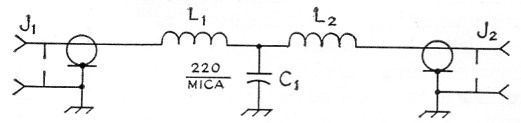
Fig. 1. Circuit diagram of the low-pass filter. The coils L1 and L2 are wound with No. 16 solid enameled wire. Each coil is 7 turns ½ inch diameter and ½ inch long. A ½ inch diameter drill shank or dowel rod can be used as a winding form. Leave an inch or so of lead length at the coil ends for connecting to J1 and J2 (phono jacks), and don't forget to scrape the enamel from the ends of the leads before soldering. A 220 µp mica capacitor, 5 percent tolerance, should be used for C1. The filter should be used with RG-58/U, RG-59/U, RG-8/U or RG-11/U coax. Of the two cables, RG-58/U and RG-59/U are less expensive and easier to handle.
For the filter to do a good job it must be shielded and properly installed on the transmitter. We want the r.f. to flow through the circuit, not around it. The customary method is to use a short length of coax line between the transmitter and the filter. The feedline terminals on the transmitter and filter must be of the coax type to maintain shielding and prevent harmonics from getting on the outside of the coax. If harmonics manage to get on the outside of the line they can bypass the filter and reach the antenna and be radiated. That is why the filter must be connected to the rig with coax line and coax fittings.
Fig. 2 shows how the filter should be used with antenna couplers or balun coils. In many instances amateurs use antennas fed directly with coax line, without benefit of a coupler. In this type of installation the filter should be installed close to the transmitter. The standing-wave ratio on the coax line should be low, say 2 to 1 or less, otherwise there is a danger of component breakdown in the filter due to excessive voltages. An s.w.r. bridge such as the Monimatch(1) can be used to determine when the line is flat (terminated in its characteristic impedance).
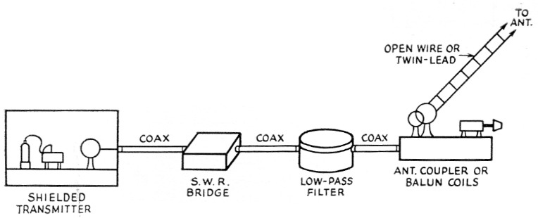
Fig. 2. This drawing shows how the low-pass filter is installed in the line between the transmitter and coupler. As mentioned in the text, an s.w.r. bridge is needed to determine when the coax is matched and the s.w.r. is low.
Fundamental overloading
If you have followed the steps outlined above you should have a transmitter that is free of harmonic radiation. However, you may still cause interference on the neighbor's TV set (or your own) due to "fundamental overloading." This type of interference, though caused by your fundamental signal, is not your fault nor obligation. However, you should be in a position to know what it is, how it is caused, and the cure.
Briefly, here is what; happens. Assuming you have a clean transmitter with no harmonics being radiated, you still have your fundamental signal going out. Receiver circuits that have sufficient selectivity to reject an adjacent-channel signal if it is of reasonable strength may not be selective enough to reject a very strong signal, even though its frequency may be far removed from the frequency to which the circuits are tuned. If the television antenna is close enough to your transmitting antenna, the signal from your transmitter picked up by the TV antenna may be so strong, even though you are operating on a frequency widely separated from the TV channel, that .the input circuits of the TV receiver will not reject it. If the signal is strong enough, one or more tubes in the TV receiver may overload. This overloading is usually accompanied by the generation of spurious signals which are then fed to other stage in the receiver, and TVI results. If the TV set had better selectivity it could discriminate against your fundamental and prevent it from reaching the r.f. tube.
The way to improve the selectivity of the TV set so that it accepts only TV signals is by means of a high-pass filter. A high-pass filter is just the opposite of the low-pass unit described earlier. In this case we design a filter that will pass only signals higher than its cut-off frequency while attenuating lower-order signals. Usually the cut-off frequency is about 40 Mc. although there are special units available with a cut-off just below Channel 2. Any of the hams who operate on 50 Mc. and have Channel 2 to deal with make good use of such filters. When high-pass filters are installed on the tuner of a TV set they usually clean up the fundamental-overload problem. The filters should be installed at the tuner and not on the back of the set. This is done to prevent any signal pickup on the lead from the TV antenna terminals to the tuner.
A good way of finding out when your own station is clean is to have a filter installed on your own TV set and be able to operate the rig without causing interference to your own set.
As we said earlier, cleaning up your neighbor's TV set is not your obligation. However, it will usually help to maintain good relations if you explain the problem to your neighbor and invite him over to see your set and demonstrate that it is clean when operating your rig. You might also point out that a high-pass filter will help reduce other types of interference. Never be discourteous, even if the TV viewer is (and many of them can be quite difficult to deal with!). Don't, under any circumstances, make remarks over the air about the neighbor or his set, he may be able to copy everything you say and you may find it difficult to keep things on a cooperative basis.
Many areas of the country have TVI committees - groups sponsored by local amateurs. These committees are equipped to handle TVI complaints and are trained to do the job. If you have complaints, contact your local committee and ask for help. If you don't know of any local groups, write the nearest FCC office, since they maintain a list of committees in each area. If there is no committee nearby to service the complaint, then you will have to handle it it yourself. This means that you must show the set owner how his set is at fault and why the installation of a high-pass filter is required. In many instances the set manufacturer will furnish a high-pass filter at no charge. The local serviceman or distributor may not know about this policy, so you may have to persuade the set owner to write to the manufacturer.
As we mentioned earlier, study the BCI-TVI chapter of the Handbook. Also, your ARRL Headquarters has printed material available that is yours for the asking. This includes sample letters to TV set owners, explaining fundamental overloading and the use of a high-pass filter, sample publicity releases, information on forming TVI committees, and other information.
Maybe you'll never have to worry about TVI, but if you do, don't forget there is plenty of help available for the asking.
Notes
- McCoy, "Monimatch mark II," QST, February 1957 or the current edition of The Radio Amateur's Handbook.
Lewis G. McCoy, W1ICP.