A simple electronic key
Better code with less effort.
In these progressive times we have a.m., s.s.b., RTTY, TV and other great improvements in radio communications, but we still have c.w., thank goodness! Although in just tuning across one of the crowded amateur bands, one would wonder if the art of radiotelegraphy has not, in many instances, been lost.
What can one do to improve his fist? Well, he might obtain a tape perforator and use tape in all his QSOs. But there is a much simpler and more economical means for the average ham to obtain tape-like perfection of his code - the automatic, self-completing electronic key. Many readers will no doubt stop here. However, if you will go a bit farther and look at the diagram in Fig. 1, you will find that a good electronic key does not have to be extremely expensive or complicated.(1)
It is true that a good many of the electronic keys proposed for amateur construction are quite complicated, while others that are relatively simple leave much to be desired in the way of operating ease and flexibility.
Just what are the fundamental requirements of a good electronic key?
- Dots and dashes must be self-completing and the key lever must be necessary only to start a dot or dash - the electronic key should then complete the character and make the required space as well.
- It should be impossible to make a dot following a dash (or a dash following a dot) without first completing the dot (or dash) and the correct space between. Releasing the key lever in the middle of a dot or dash should not affect the length of that character.
- The speed control should be continuously variable from about 5 to 50 words per minute.
- The key switch circuit should be adaptable for use with a slightly modified semiautomatic bug or a simple home-made key lever.
- Provisions should be made for an adjustable dot-to-dash ratio. Slight deviations from the accepted ratio of one to three sometimes allows easier sending.
- Weight of keying (dot-to-space ratio) should also be variable to meet the requirements of different transmitters and keying techniques. Here again, the accepted ratio of one to one may not suit the requirements of all operators.
- The circuit should be mechanically and electrically stable. Ordinary variations in line voltage should have little or no effect on the performance of the circuit. Adjustments should not require critical attention.
- There should be no interaction between the three controls: speed, dot-dash ratio and weight of keying. Changing any one of these should not affect any other.
- And last, but by far not the least, the circuit should be simple, using the minimum of easily obtained standard components.
I would like to present an electronic key that will meet all of these requirements. The only one of these requirements that leaves anything to be desired is number 8. When the speed is changed there is a slight change in the dot-to-dash ratio. However, this change is quite small and is entirely unnoticeable unless an extremely wide change of speed is made. Within the usual limits of 10 to 25 w.p.m., there will be no difficulty.
The circuit
As shown in the schematic, Fig. 1, the circuit requires only one tube, a triode-connected 6AQ5. This tube is normally biased beyond cutoff by the drop across the 5000-ohm cathode potentiometer. Relays K1 and K2 are not energized in this condition.
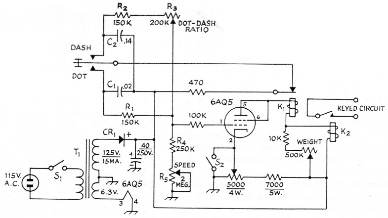
Fig. 1. Circuit diagram of the electronic key. All capacitances are in pF, all resistances are in ohms, all resistors are ½ watt unless otherwise indicated.
| CR1 | 65 mA selenium rectifier (Federal 1002A or equiv.). |
| K1,K2 | 9000 ohm plate circuit relay (Sigma 11F-9000- G/SIL or equivalent). |
| Sl,S2 | S.p.s.t. toggle. |
| T1 | 125 V 15 mA ½ wave secondary and 6.3 V 0.6 A heater winding (Stancor PS-8415). |
Upon application of the supply voltage, both C1 and C2 charge to its value, about 150 volts. When the key lever is pushed to the dot position, C1 discharges very quickly through the 470-ohm resistor. At the same time the grid of the 6AQ5 is driven positive by the current flow through Ri, R4 and R5. This causes the tube to conduct heavily and energizes both K1 and K2. When K1 is energized, the discharge path for C1 is open and it is permitted to charge to the supply voltage again. This charging current flowing through R4 and R5 keeps the grid positive and the relays energized after K1 has opened and B+ has been removed from the resistors in the grid circuit. When C1 becomes recharged, the grid is no longer positive and K1 is de-energized and the discharge path for C1 is again closed. If the key lever is still in the dot position when K1 is de-energized, the cycle will repeat. When the key lever is in the dash position the operation is similar except it takes longer for C2 to charge because of its higher capacitance. Now both dots and dashes are automatic with the key lever locked out until the character and space have been completed.
R1 and R2R3 provide adequate isolation between C1 and C2. Complete isolation would require another tube and is quite unnecessary. R5 varies the charging time for both C1 and C2 and thus controls the sending speed of the key. Relay K2 is shunted with an adjustable resistor. This allows K2 to become de-energized at a higher plate current than K1. By adjustment of the 500K weight control, K2 can be made to open at any time during the charging time of C1. This controls the weight of keying.
S2 is a normally open switch or push button; when operated it causes K2 to close so that the transmitter can be tuned.
Adjustment
After the key is wired and B + applied, the following procedure should be used for initial tune up. A code oscillator connected to the contacts of K2 will be very helpful at this stage. If everything is working properly, both relays should operate when the key lever is pushed to either the dot or dash position. Adjust R5 for a speed of about 8 to 10 words per minute. The weight control should be turned so that all its resistance is out of the circuit. Now, while listening to the key through the audio oscillator, adjust R3 for the proper ratio. This should be a one-tothree ratio, and a little patience will give just the right sound. Now advance the weight control for proper weight of keying. Its final adjustment should be made while keying the actual transmitter under normal load and listening to the signal on the station receiver. The keying circuits in some transmitters -tend to change the weight of keying. The 5000-ohm cathode potentiometer should be adjusted for about +35 volts or so on the cathode of the 6AQ5. Then while listening very closely to the dots (keying the code oscillator) make very small adjustments of the cathode control in the direction that tends to slow down the speed of the key, until all the dots at any spe^ific speed are the same length. If this adjustment is not correct the first dot of a series of dots may he shorter than the following. There is some interaction between controls during tune-up, so all adjustments should be touched up again.
The author's model was built into the case of a Mon-Key. The entire circuit, along with the power supply, was included on the chassis, thus making a very compact arrangement. The only controls that need to be accessible are S1, S2 and R5, the speed control. All the others may be under cover and made screwdriver-adjustable.
An ordinary semiautomatic bug may be easily modified for the key lever. Remove the weights from the bug lever, adjust the dot contacts for positive closure without vibration, and remove the jumper between the dot and dash posts. The modified bug is then connected to the proper points on the electronic key with a three-conductor cable.(2)Relays
And now a few words about the relays used in the circuit. I used an 8000-ohm, Terado Micro relay for K1 and an Advance 10,000-ohm, plate-circuit relay for K2. These relays were used because they were available at the time. Other relays have been used, and as long as they are sensitive and fast acting they seem to operate very well. The Sigma 11F-9000-G/SIL plate circuit relays will work at both K1 and K2. These relays are quite small and relatively inexpensive, and they should be used if cost is to be kept at a minimum. Many of the relays on the surplus market will give good service.
After using this key for about two years and listening to the comments about it on the air, I can think of only two improvements that might be incorporated into it. One is the elimination of at least one relay, and the other is the addition of a dot anticipator. However, these complicate the circuit and defeat the purpose of a simple inexpensive electronic key. After all, the Ultramatic has all these features and many more!
If one is accustomed to a hand key it should take only a few minutes to get the "feel" of this electronic key because it does almost all of the work, except spelling. If the operator has been using a semiautomatic bug, it may take a bit longer for him to realize that those dashes are automatic too! It is almost impossible to send poor code with this key. Characters cannot be cut short nor can they be run together. As an example, let's make the letter "N." Push the key lever to the left (dash position). Just as soon as the dash has started, move the lever to right (dot position). The automatic key will finish the dash, make the proper space and begin the dot. Just as soon as the dot has started, move the lever to neutral. The key will finish the dot and stop. Try this at a very slow speed to realize just how automatic it is!
So if you really want to sound like W1AW, put this gadget together. It will take only a few hours and will repay you many times in ease of operation and almost perfect c.w.
Notes
- Geppert, "A single-tube electronic key," Radio & Television News, October, 1950.
- If you don't have a bug key to convert for the lever, ideas on lever construction can be found on page 36 of February, 1955, QST; page 35 of April, 1955, QST; and on page 48 of February, 1957, QST. - Ed.
Roy G. Foster, K0HLC.