The C.W. man's friend
Who burns the midnight oil?
What source those nervous clicks and clacks that punctuate the evening air?
All's revealed! The dreadful sight's disclosed!
And who's the wretch our shuddering eyes behold?
A c.w. man! A binary boob!
And worst of all
This article's meant for him.
An all-purpose keying unit.
This is a description of a precision general-purpose keying and control device to provide flexible break-in control of a complete station. It uses small, standard, inexpensive relays as the actual control elements, since no other arrangement allows as much flexibility with equivalent electrical performance.
What it is
The input is the usual telegraph key. The outputs are two sets of relay contacts, arranged to operate in a controlled sequence. One circuit, which will be referred to as the oscillator circuit (V1 and V2A in Fig. 1), controls the transmitter oscillator, the receiver break-in gain control, the antenna switch or relay, the final amplifier bias (for noise suppression purposes), etc., as used in any particular station. The other circuit, which will be referred to as the amplifier circuit (V2B), controls the keyed amplifier, the monitoring oscillator, etc., as used. The actual outputs are sets of relay contacts to be used as desired in performing the operations listed above. Up to three singlepole-double-throw contacts may be used in the oscillator circuit, and either one or two s.p.d.t. contacts may be used in the amplifier circuit, one relay being required for each s.p.d.t. contact.
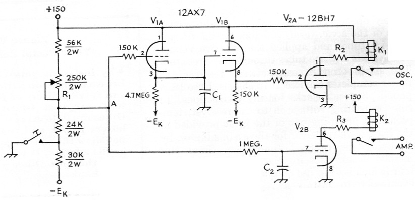
Fig. 1. Circuit diagram of the break-in keying unit. Unless otherwise indicated, resistors are ½ watt. The 24K and 30K resistors are 5 % tolerance. See text for values and adjustment of C1, C2, R1, R2 and R3. Two or three relays can be used in parallel at Ks; two relays can be used in parallel at K2.
K1,K2 12 volt 1350 ohm s.p.d.t. relay (Potter & Brumfield RS5D).
The sequential operation is as follows: on "make" (when the key is closed) K1 picks up immediately, but K2 pickup is delayed for a time proportional to the value of C2. This allows the oscillator clicks and chirps to get over with, the receiver to get turned off, etc., all before the keyed amplifier controlled by K2 passes any signal. On "break" (when the key is opened) K2 drops out almost immediately, but K1 is held up for a time proportional to the value of C1 to allow the keyed amplifier to cut off cleanly the transmitter output before the oscillator is turned off and the receiver turned back on.
Necessary adjustments
Because a range of negative voltage, Ek, and component variations were allowed for, there are three adjustments that must be made when the keyer is initially put into operation. For best performance these adjustments should be checked occasionally to allow for gradual drift in component values as the unit ages.
The first adjustment to be made is the 250,000 ohm potentiometer, R1, that adjusts the level of the input control signal. It should be set to give the two voltage levels indicated in Fig. 2. A highinput-impedance voltmeter should be used for this measurement, preferably a v.t.v.m. or 20,000ohms-per-volt multimeter. If things are working normally there will be a little extra voltage swing available. Adjust the pot so that the excess swing is about the same in each direction.
The next adjustment is the relay resistors R2 and R3. Adjust each so that 12 volts, or a little over, appears across the relay coils when the key is closed. Typical values for these resistors are: one relay, 8200 ohms; two relays, 2200 ohms; three relays, 1000 ohms.
The final adjustments are the delays controlled by C2 and C1. The amplifier keying should first be adjusted(1) as desired, with the keyer functioning only to drive K2. This may be done conveniently by grounding pin 2 of V2n to hold the oscillator on, and temporarily removing C2 from the circuit so there is no delay. After the keying circuit connected to the contacts of K2 has been adjusted satisfactorily, restore the keyer to its original condition. Now gradually increase the value of C2 until the output signal of the transmitter on make sounds just as it did when the keyer was not functioning. Because of the inherent time delays in the relays, it may be found that C2 can be omitted entirely.
After C2 has been adjusted, adjust C1 to the minimum possible value that does not clip the transmitter output signal on break. For most transmitters both C2 and C1 will probably end up within a factor of ten of 10 nF. The use of decade capacitors is very convenient in making these adjustments.
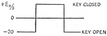
Fig. 2. Voltages to chassis at point "A" (Fig. 1) for proper operation of the keying unit.
Technical discussion
The keyer may be operated with any negative voltage supply, Ek, from 60 to 150 volts. The current required will range from 2.5 ma. at 60 volts to 6 ma. at 150 volts. The 150 volt positive supply current can be calculated from the following equation: 5 + 9N (N = number of relays) ma. Thus if two relays are used at K1 and one relay is used at K2, the total positive current will be about 32 ma. These supplies should be reasonably well regulated, preferably by VR tubes. If this is a problem, V2 may be supplied by a source of somewhat poorer regulation, leaving only 5 ma. at + 150 volts that must be well regulated. The decision to use relays as the primary control elements was due to their flexibility. Practically any kind of control circuit can be made to work from relay contacts, so their use allowed the keyer to be designed with practically no thought as to the circuits to be controlled and their voltage and current requirements. Anyone who has tried to replace a relay with a vacuum tube, particularly when the final use of the circuit is unknown, will appreciate the convenience involved. The relays are all 12-volt s.p.d.t. Potter and Brumfield type RS5D, with 1350-ohm d.c. coils; they cost $2.70 each. They are quite adequate at speeds up to about 30 w.p.m., allowing a breaking station to be heard through a string of 25 w.p.m. dits. For higher speeds it is suggested that Stevens-Arnold Millisec relays be used, which cost around three times as much.
The K2 circuit is practically a straight relay control circuit. The 1 megohm resistor limits the grid current of V213 and in conjunction with C2 creates the delay in the pickup of K2 on make. There is also a slight delay in the drop out of K2, but it is not long enough to be significant.
The K1 control circuitry is a little more subtle. VIA is used as a driver for the break storage capacitor C1, and Vin as a cathode-follower driver for V2A. The capacitor charges through VIA in less than a millisecond after the key is closed, but when the key is opened VIA is cut off and the capacitor must discharge through the 4.7-megohm resistor, giving an appreciable delay before V2n is cut off and K1 opens. There may be a little delay on make as a result of the closure time of K1, but probably not more than 10 milliseconds, and it is automatically allowed for in the adjustment of C2.
If the key spark causes an objectionable amount of r.f. noise in the form of clicks when the key is opened or closed, correction measures should be limited to placing an r.f. choke in series with the key as close to the key contacts as possible. The shunt capacitors of the usual click suppression circuit might slow up the waveforms too much.
Notes
- For a discussion of keying adjustments, keying circuits, and receiver control, see the keying section of the current Radio Amateur's Handbook.
T.H. Puckett, W5JXM.