A multiband antenna system for the newcomer
Combination antenna coupler and matching indicator.
If you have been searching for a multiband antenna system this article should be of considerable interest to you. We will describe an antenna coupler for the 3.5- through 28.0-Mc. bands that has a built-in standing-wave ratio bridge. The s.w.r. bridge can be used for matching and as an output indicator. Also included in the article is the description of a multiband antenna. Whether you are a Novice or General this may be exactly what you have been looking for.
You may have read or heard that an antenna coupler is an unnecessary item in the ham station. Before going any farther let's see what a coupler is and what it can do for you.
Why An Antenna Coupler?
Many newcomers to amateur radio elect to use antenna systems that do not require antenna couplers. Such systems as multiple dipoles, traptype antennas, and the off-center-fed type have become quite popular. The reason for the popularity of these systems is that they can normally be attached directly to the transmitter (with a feed line, of course), and be made to work. When an antenna system is used that requires a coupler, the coupler must be adjusted in order for the system to work. As the systems mentioned above do not require couplers it can be said that they offer "operating convenience." However, to mix a metaphor, you cannot have your cake and get it for nothing! There are many excellent reasons why a coupler should be used and they far outweigh any operating conveniences of the non-coupler type of installation.
First, and most important from the Novice's viewpoint, an antenna coupler usually eliminates the harmonic problem. We are speaking now of the common problem of second-harmonic radiation (7.4 Mc) from 3.7 Mc operation. We know that a large number of newcomers are cited by the FCC each month for harmonic radiation. With the system described in this article the Novice can be reasonably sure he isn't going to get into trouble with the FCC.
In many instances the use of a coupler will eliminate the harmonic TVI problem. If sufficient harmonic attenuation is not achieved with the coupler, a low-pass filter must be used; here again a coupler plays a very important role.
A low-pass filter is designed for a particular impedance of coaxial line, usually 50 or 75 ohms. This line must be reasonably flat (have a low standing-wave ratio), in order to prevent damage to the filter components. It is difficult to keep the s.w.r. low on feed lines used with the types of antennas mentioned earlier, at least on all the amateur bands and frequencies. However, it is a very simple matter to take care of this problem when using a coupler. The normal procedure is to connect the transmitter to the coupler via a short length of coax line. By adjusting the coupler the coax line can be kept perfectly flat on any frequency within the amateur bands. The ideal place to install the filter is in this length of line.
In many instances, it may become difficult or impossible to couple power from the transmitter to the antenna because the coupling circuit doesn't have enough range. This deficiency can be eliminated by the use of an antenna coupler. With the system described here it is possible to adjust the coupler so that the transmitter is always working into the best load for its coupling circuits.
The antenna system we will describe uses open-wire feeders and here is another advantage in using a coupler. Of all the types of lines used by amateurs, open-wire feeders have by far the least loss. Also, many other types of lines can be affected by moisture so that their characteristics change. Open-wire feeders are not affected by m isture, at least not as much as some other lines.
Al too many amateurs think of an antenna cou ler only in terms of transmitting. By installing the antenna change-over relay or switch bet een the transmitter and coupler the latter can used on the receiver. If you don't think this can be a big help just ask any amateur who uses such a setup. The coupler provides, in many cases, additional selectivity for the receiver. Strong commercial signals outside the ham bands have a nasty habit of getting into the receiver, causing image troubles or cross modulation. A coupler helps to reduce this problem.
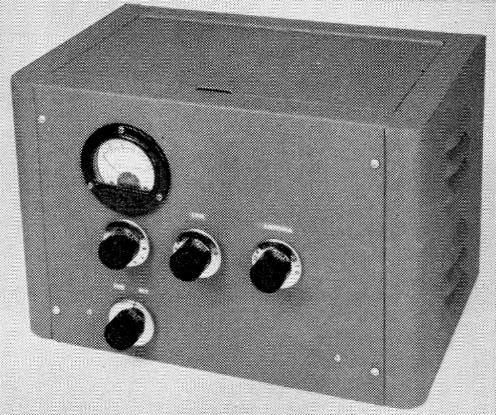
At the right is the knob for C1, the center knob is for C2, and the sensitivity control is at the left. The knob at the lower left is for S1.
Before getting into the actual construction of the coupler let's take up one more point that the newcomer may not be familiar with - series- or parallel-tuned feed lines. The main purpose of a coupler is just what the name implies, to couple the power from the transmitter to the antenna feed line. The end of the feed line that is attached to the coupler presents a load to the coupler. With a high s.w.r. whether this load is high or low impedance depends on the electrical length of the feed line and antenna. If it is low it is easy to couple power from the transmitter if a series-tuned circuit is used in the coupler. When the load is a high impedance, parallel tuning should be used. We'll show you how to design your antenna and tell you what type of tuning is required in a moment but first let's take a look at the coupler.
The antenna coupler
At first glance, Fig. 1, the circuit of the antenna coupler, may appear complicated. However, don't be scared away; it is actually quite simple. The method of changing from series to parallel tuning while maintaining coupling at the center of the antenna coil is a novel one cooked up by W1DX. As you will find when you read the section of the article on the antenna, the use of series or parallel tuning will depend on the antenna and feeder lengths.
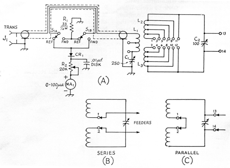
Fig. 1. (A) Circuit diagram of the antenna coupler and s.w.r. bridge. (B) Series tuning. (C) Parallel tuning.
| C1 | 250 pF variable capacitor (Hammarlund MC-250-M). |
| C2 | 100 pF variable capacitor (Hammarlund MC-100-SX). |
| CR1 | 1N34A germanium diode. |
| J1 | Coaxial chassis receptacle, SO-239. |
| L1,L2,L3 | See Fig. 2 and text. |
| MA1 | 0-100 microammeter, or other range, depending on sensitivity required. |
| R1 | 33 Ω, ½ watt carbon resistor. |
| R2 | 20 kΩ potentiometer. |
| S1 | D.p.d.t. "tone control" switch (Centralab 1462). |
In order to show how the coupler is used for series or parallel connections, we have drawn two simple circuits in Fig. 1, B and C. For series tuning, the feed line is attached to terminals 1 and 2. This splits the antenna coil into two equal parts and puts them in series with the line. When parallel tuning is required terminals 1 and 2 are shorted with a jumper and the feed line is connected to 13 and 14.
Band-changing the coupler is accomplished by shorting out portions of the coils L2 and L3. The taps and leads from the coil are wired to pin jacks that can be connected together with shorting jumpers. Normally, the unused portion of the coil should be jumped with the shortest possible line. However, no ill effects were apparce nt in testing and using the coupler as shown. We had considered a switch for making the coil changes but a suitable switch, one that would fit the requirements of voltage breakdown and mechanical layout, was impossible to find - at least, at prices we were willing to pay. The pin jacks and plugs cost only a few cents each.
The coupler as described will easily handle the Novice 75-watt power limit. Any readers using transmitters in the popular 150-watt class can alter the coupler for this power level by using a variable capacitor with adequate voltage rating for C2. The coil stock used for L1, L2 and L3 should safely handle about 300 watts without overheating so the controlling factor is the r.f. voltage rating of C2.
The s.w.r. bridge utilizes a length of RG-58/U to house the pickup wire of the bridge.(1) A double-pole switch is required to switch the pickup lead ends so that either forward or reflected power can be fed to the indicating circuit.
Construction
The unit shown here was built on a 2 × 7 × 9 inch aluminum chassis which is housed in a Premier H.T.C. 201 cabinet. If the reader elects to use a bigger capacitor (greater plate spacing) for C2 a larger chassis than the one specified would be more suitable. Layout of the components is not critical but it is a good idea to use the photographs as a guide.
Fig. 2 is a drawing of the three coils, L1, L2, and L3. These three coils are all part of a single length of B & W 3907-1 coil stock. This material is 2 inches in diameter, 10 turns per inch, No. 16 tinned wire. Before attempting to make the coils for the coupler, study Fig. 2 so that you are completely familiar with the drawing. With a ruler measure off 68 turns (613/16 inches) and cut this piece from the original stock. A hacksaw is a good tool for cutting the stock support bars. Unwind one turn from each end of the piece. This will leave a 66-turn coil. Count ih from the end of the coil and cut the wire at the 26% turn. Do this at each side. We used a pair of side cutters to make the cuts and slightly bent the adjoining turns away from the cutting point in order to get at the wire. Unwind a half turn from these points and this will leave you with three separate coils, all on the same support bars. Refer to Fig. 2 for the tap points. You'll find that if you bend the wires adjacent to the tap points in toward the axis of the coil you'll have plenty of room to solder the tap leads onto the coil.
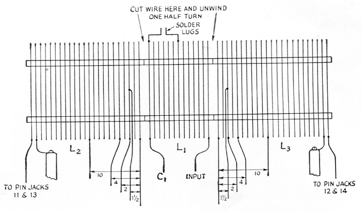
Fig. 2. Drawing of the antenna and link coils, L1, L2, and L3. The numbers indicate the terminals to which the coil taps and leads are connected.
Two steatite pillars are used to support the coil on the chassis. The bottom of the coil is high enough to clear the rotor of C2 when it is open. Sensitivity control R2 is mounted on the panel below M1.
The link, L1, is too large for 14, 21 and 28 Mc, so part of it must be shorted out when using these bands. Two soldering lugs should be soldered to the 1st and 6th turns of the link counting from the C1 end. The lugs are mounted at the top of the coil and bent so their ends are close together. An alligator clip can be used to short the two lugs. Use a copper clip as iron tends to heat up when used in r.f. power circuits. Incidentally, this is an important point to remember when doing any transmitter construction work involving r.f. circuits. Iron or steel will heat up and actually steal power from the circuits. Use nonmagnetic hardware for mechanical connections wherever possible.
Two steatite standoff insulators, ½ × 2½ inches (Millen 31002), are used to support the coil. Soldering lugs should be soldered to the first turn on each of the two outside coils. The lugs are then mounted on the standoffs (see Fig. 2).
Steatite standoffs, ¾ inch high (Millen 31011), should be used to mount C1 and C2 on the chassis. Both the rotor and stator of C2 must be insulated from the chassis and cabinet panel. An insulated coupling should be used on the rotor shaft (Millen 39006). A steatite through-chassis insulator (E. F. Johnson 135-40) is used for the input connection to bring the lead up to C1.
The coil taps and ends (terminals 1 through 14) are brought below chassis top through four rubber grommets, two ¼ and two ½ inch. Sockets for terminals are Amphenol type 78-1L, 14 being required. The sockets mount in 3/8 inch holes and are held in place by retaining rings. A simple method for mounting a socket is to place it in the hole, slip the retaining ring over the end and then use a short piece of %2-inch diameter pipe to force the retaining ring over the socket. Six plugs, Amphenol 71-1L, are needed for the shorting plugs. The wires for the two longer shorting lines are 3 inches long and the short one is 2 inches long.
Matching indicator details
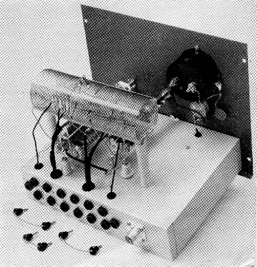
A 24 inch length of RG-58/U is needed for the s.w.r. bridge circuit. The first step is to remove the vinyl covering from the cable. If you score the covering with a knife blade the material can be peeled off. A 14-inch length of No. 20 solid tinned wire, plastic insulation (Belden 8529), is used for the bridge pickup wire. Mark the braid on the coax 6 inches from one end and 4 inches from the other. Next, bunch the cable together and with a sharp pointed tool make a small opening in the braid at the marked points. Feed the pickup wire under the braid, in one opening and out the other. Stretch the braid out along the cable until about one inch of the pickup wire projects from each opening. Look at the bottom view of the coupler and you will see how the coax is coiled up so that the two pickup wire ends are close to switch contacts. Once we found the correct configuration, a short length of tinned wire was wrapped around the braid and soldered. This holds the assembly in place and makes it easier to handle.
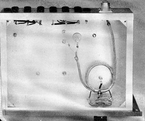
This view shows the method for connecting the coax input line and pickup wire. The terminal jacks for the coil leads and taps are mounted along the rear chassis wall.
The terminating resistor of the bridge, R1, is a half-watt carbon 33 ohm unit. Be sure to use a carbon resistor, not wire-wound. A rubber grommet should be installed in the chassis top directly over the switch. This opening is for the lead from the 1N34A diode that goes to R2. When soldering the diode leads hold the wire with a pair of long-nose pliers between the body of the diode and the point being soldered. This will conduct the heat away from the diode, thereby preventing damage to the unit. The sensitivity control, R2, should be mounted below the meter.
The antenna system
Before discussing adjustment procedures let's take a look at the antenna system. There are a few simple rules that should be followed (if possible) when installing an antenna. Try and get the antenna as high as possible. Also, keep it clear of nearby objects. In other words, don't run it alongside rain gutters or through branches. Dress the feed line away from the antenna at right angles, or as near so as possible. Many amateurs bring their feed line straight down from the antenna to a post or support and then into the shack.
However, if you cannot follow the above rules, it doesn't mean an antenna won't work. For example, if you are cramped for space you can drop the ends of the antenna down in order to increase the length. If the antenna must run near metal objects don't scrap your plans. Put the antenna up and try it; you may be pleasantly surprised.
How long should the antenna be? The answer to this question depends primarily on the lowest frequency band you plan on using and, of course how much space is available. We will assume that you want the antenna for 3.5 Mc. as the lowest band. If it is long enough for this band it will be adequate for the higher bands.
Fig. 3 gives the information you'll need to find the antenna and feeder lengths. The length of the antenna, A, should be at least a quarter wavelength long at the lowest frequency band. Otherwise, the effectiveness of the antenna will suffer. When you make the system according to the formula ½A + B equals a quarter wavelength, or multiple thereof, you will simplify the coupling problems. For an odd number of quarter wavelengths you will use series tuning at the coupler, and for an even number, parallel tuning.
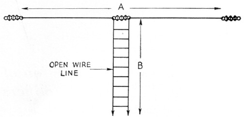
Fig. 3. The length A should be more than a quarter wavelength at the lowest operating frequency. When you determine the length of A to half the distance, add a sufficient length of feed line (B) to equal a quarter wavelength or multiple thereof. For example, let's assume you can put up an antenna 80 feet long and you plan to operate on the 3.7-Mc. Novice band as the lowest frequency. From the formula 246 / 3.7 = 66.5 feet 66.5 - 40 = 26.5 feet the feeder length, or 2 × 66.5 = 133 133 - 40 = 93 feet. This can be carried out for greater feeder lengths, depending on the requirements of the installation.
A common problem is finding enough space for the antenna, the average city lot being too small for a half-wavelength antenna on 3.5 Mc. As mentioned earlier, the antenna can be shorter than a half wave and still work. The feed line can be lengthened or shortened to make the system fit the formula.
You can make your own open-wire feeders or use the TV-type open-wire line. Don't use solid-dielectric Twin-Lead for the feeders; this type of line is satisfactory for some types of feeders but not in tuned lines. You can use a short run of the transmitting type Twin-Lead to go from the coupler to the feed-through insulators on the wall of the shack. The insulated Twin-Lead will simplify your installation problems, but don't use any more than you have to. For the antenna, you can use No. 14 Copperweld or a similar type. (Electric fence wire makes good antenna material.) Use soft-drawn wire in a homemade feed line.
Getting the system working
Connect the coupler to the transmitter with a length of 52 ohm coax, either RG-58/U or RG8/U. If you are using a low-pass filter it should be installed in this length of line. Also, the antenna relay should be inserted at this point. Attach the feed line to the coupler and make the connections for series or parallel as required. (See Table 1.) Set R2 in the indicator circuit at maximum resistance and switch Si to reflected power. Tune up the transmitter and resonate the final amplifier for plate meter dip. If you have an output drive control it is a good idea to tune up with reduced output. Next, adjust C1 and C2 in the coupler for minimum reading on the s.w.r. indicator. You will probably have to decrease the resistance of the potentiometer, R2, in order to get a reading. When C1 and C2 are adjusted for minimum reading (this is usually zero or close to it), switch Si for forward power and set R2 for about half-scale meter reading. Now you can tune up the transmitter for full loading as indicated by your plate meter and the bridge meter. You may have to reduce the setting of R2 to keep the needle on scale. Incidentally, once your coupler is adjusted for the minimum reading or matched condition you don't have to change the coupler adjustments for that particular frequency. All loading adjustments are made at the transmitter.
| Parallel | Series |
|---|---|
| Connect feeders to 13 and 14, jumper 1 and 2 | Connect feeders to 1 and 2 |
| Short following terminals with jumpers | |
| 3.5 Mc | |
| 7.0 Mc | ll and 9 - 12 and 10 |
| 14.0 Mc | 11 and 7 - 12and 8 |
| 21.0 Mc | ll and 5 - 12and 6 |
| 28.0 Mc | 11 and 3 - 12 and 4 |
Mark down the control settings of the coupler for this particular frequency and then proceed to the next higher band. Keep a record of the settings and it will be a simple matter to set the coupler up in a hurry.
If you should find that you cannot get a matched condition on some band, you may have to try different tap points. However, be sure to try both series and parallel tuning first.
If you are looking for additional information on antenna masts, how to support the antenna, construction of feed lines, and so forth, we suggest you study The Radio Amateur's Handbook and The A.R.R.L. Antenna Book.
Notes
Lewis G. McCoy, W1ICP.