"Just like QST, Except ...."
Some hints on stabilization of tetrode and pentode amplifiers
The four words of our title are encountered almost daily in mail handled by the ARRL Technical Information Service. They are also voiced frequently by visitors to the ARRL Lab, who tell us their troubles with equipment they've been building. Often it turns out that instability trouble these fellows have is the result of common misconceptions as to right and wrong methods of bypassing and grounding in tetrode and pentode amplifiers.
We neither expect nor want everything built from QST and Handbook information to be exact duplication of the original. To be of greatest value, equipment descriptions should be used for ideas to be incorporated in gear of your own design. If QST and Handbook articles were used only for exact duplication they would not be making the most of the time and money spent on them. The important thing is to know what to change, and what to leave as the original designer made it. Methods employed in bypassing and grounding should be in the latter category.
To some extent each new amplifier represents a design problem. We would not have you believe that every transmitter or converter built in the Headquarters lab is stable right from the start. But from long experience we have become well acquainted with some of the more common forms of instability. These have all been discussed at one time or another, but a summary may still be in order, especially in view of the fact that assembly details we'll be talking about often do not come through well in photographs. Even an experienced builder of ham gear may find it hard to know just where to put a bypass lead or a grounding lug, no matter how well the pictorial and descriptive details are set forth in print.
Certain tubes have a reputation of being hard to tame. The 807 was such a dog for many hams for years, and the evil reputation it built up, largely unjustified, is now inherited (with even less justification) by the 6146. It is true that tetrode and pentode tubes, having very high power sensitivity, may require neutralization, but more often than not the trickiness involved in getting an amplifier to operate stably is the result of violation, by the designer, of certain cardinal principles. If you yearn for the "good old days" of easily neutralized triode amplifiers it may be that you've been building in some troubles for yourself.
Put the socket above the chassis!
Many a lab headache has been relieved like magic by the simple expedient of taking out a socket that was mounted below the chassis and putting it on the tube side of the chassis or mounting plate. This became really important when we started building transmitters that had to work on many bands without readjustment of neutralization. Cause of the oscillation trouble with sockets mounted under the chassis is often the long plate-cathode return. This return cannot be made effectively via screws going through the chassis. The actual path (and you can often trace it by chassis "hot" spots) is around the edge of the chassis, or through some large hole. Some considerable portion of the chassis thus becomes common to both plate and grid circuits, and the resultant feedback is difficult to neutralize out.
This sort of thing may not be troublesome in an amplifier designed for a single band, though even here it may make the neutralization job fussier than it should be. But in an amplifier for several bands the effect of coupling through common ground paths varies with frequency. Your amplifier requires neutralization on some bands but not on others, or the degree of neutralization cannot be set up right for several different bands. Having gone through this with more amplifiers than we care to recall, we now put the socket atop the chassis first, instead of making ourselves an almost certain revamping job by mounting it in the "conventional" manner.
Cooling down the screen
Once the socket is mounted above the chassis. the method of bypassing is still important. The screen and cathode must be at zero r.f. potential or there's going to be trouble. The screen is the villain in some amplifiers that should be stable but aren't. To cool it off, bypass right at the screen terminal or terminals. If there is more than one screen pin, bypass each one separately, right to the chassis, with no leads. Forget the old precept of a common ground bus, or a common grounding point. The chassis is the place to go with bypasses, and without any wandering!
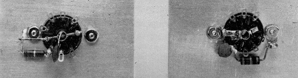
Models illustrating right and wrong methods for bypassing and grounding terminals of a 9-pin miniature socket. Both show Pins 4 and 9 grounded, with a cathode resistor and associated bypass capacitor connected to Pin 3. In the wrong approach, left, a wire is run from Pin 9 through the center shield and Pin 4, to a grounding lug. The bypass is made from Pin 3 to the center shield, making its path to ground common with other circuits. In the example at the right, the pins to be grounded and the ground lug itself are bent tightly against the cylinder and soldered in place. Bypass is grounded at the bottom of the lug.
Ordinary bypassing may be ineffective in v.h.f. amplifiers, especially for 144 Mc. and higher. Then some form of screen tuning becomes necessary. Examples will be found in all recent editions of the Handbook. Such circuits usually involve series-resonating the screen circuit to ground, to provide a path of lowest possible impedance.
Occasionally you will find a circuit in QST or the Handbook in which no screen bypass is shown. These bring inquiries as to whether an error was made, and what value bypass should be used. Diagram readers are accustomed to seeing screens bypassed, and they can't imagine it not being done. Sometimes the circuit is a frequency multiplier, and in that case it doesn't make much difference whether the screen is cold or not. Why waste a capacitor, in that event? At 220 and 420 Mc. several factors come into play that may make screen bypassing unnecessary. The screento-ground capacitance within the tube may be. enough to do the job at these frequencies. More important, degeneration due to cathode lead inductance, and loading of the tuned circuits by the tube, may cut the power sensitivity of the amplifier to the point where self-oscillation is not the problem it is on lower bands.
The hot cathode
Oscillation troubles are often built into tetrode or pentode amplifiers by inserting a keying jack in the cathode lead. The cathode has to be cold, too; perhaps even more so than the screen. In the 50 and 144 Mc exciters in the Handbook you'll notice that the 50 Mc job has cathode keying; the 144 Mc one does not. That's because small disk ceramics (probably the best v.h.f. bypasses available at low cost) are effective at 50 but not at 144 Mc. That 144 Mc cathode (2E26 or 6146) could probably be cooled down by some special circuit tricks, but we found it simpler to resort to some other method of keying, and left the cathode grounded by the shortest possible lead, in the rig for the higher band. Grounding each cathode lead separately may be desirable with the 2E26 and 6146.
Bypasses that don't bypass
Oscillation troubles are not confined to transmitters, as any v.h.f. converter builder knows. And oscillation is not always where you'd expect to find it - in a pentode or neutralized-triode amplifier stage. We've seen quite a few "grounded-grid" stages that took off all over the place because the grid was not actually grounded. In several instances a wire lead was run from the cylindrical shield in the center of a miniature socket to a ground lug at one or both sides of the socket. Bypass capacitor leads were connected to the cylinder, or to some point along the wire, rather than to the lug, right at the chassis.
The effect of r.f. voltage building up on a ground lead, perhaps no more than a quarter inch long, can be observed by running the stage in an oscillating condition, and then probing for hot spots with a pencil lead. If the stage is in a receiver, you can listen for scratching sounds. If it is a transmitter, watch the grid current in the offending stage.
In a 50 Mc transmitter built for the 1959 edition of the ARRL Handbook we ran into trouble with a 6146 stage that refused to neutralize. We tried several methods; each would come close, but not quite do the job. In this rig we had abandoned the principle discussed earlier and mounted the tube socket below the chassis, primarily to save over-all height. With just one band to worry about, we felt the calculated risk worth taking.
In this amplifier both the screen and cathode leads were hot. Touching the screen or cathode terminals caused a flicker in the small amount of grid current that persisted in the 6146 stage, when drive was removed. In desperation we pulled out the socket and put a different type in its place - and at once the capacity-bridge neutralization system we'd been wrestling with for days neutralized the stage out as easily as anything we've ever worked with.
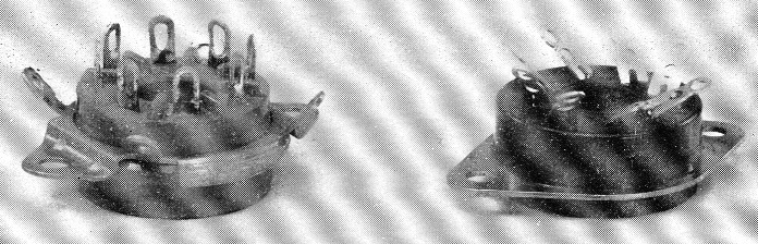
Tube socket with built-in grounding ring and four lugs (left) is an invitation to trouble due to common ground paths. Flange between lugs may not contact chassis, in which case connections made to lugs have long path to ground. Socket at the right necessitates grounding to chassis or to lugs under mounting nuts, making it possible to avoid common ground paths.
The cause of all the trouble was the same old bugaboo, common ground paths, in a somewhat different form. The socket was a popular make having a metal grounding ring in a slightly different plane from the ears that mount the socket to the chassis. There are four lugs extending from the ring that are intended for grounding points. They may be suitable for that purpose at lower frequencies, but in a v.h.f. amplifier the lugs and ring provide a built-in common path for the circuits grounded or bypassed thereto. We've had at least two hassles with sockets of this type in recent lab experience, but this writer will have no more!
Quite a bit of new manufactured gear employs a device that was all but discarded years ago, the so-called wafer socket. In the days of the "low-loss" insulation craze we looked down our noses at anything but ceramic insulation. Now we know that most other insulating materials are good enough, at least in low-voltage applications, and that the physical construction of the socket as to lead lengths may be more important. The flat wafer socket has a distinct advantage in this respect. If the chassis is a material that will take solder readily, socket terminals to be grounded can be soldered directly to the chassis, resulting in much lower lead inductance than is possible with bulkier ceramic or molded bakelite sockets.
From all this discussion it can be seen that there are more causes of instability than first meet the eye. With triodes the main cause of oscillation is the considerable grid-plate capacitance of the tube or tubes. We neutralize this out with a capacitance that is approximately the same as the tube grid-plate capacitance, feeding back energy 180 degrees out of phase with that fed through the tube, and the job is done. The power sensitivity of triode tubes is low, so the neutralization process is fairly routine. (We didn't think so back in the '30s, however!)
Tetrodes and pentodes have additional tube elements that keep their grid-plate capacitance at a very low value, usually under 0.1 µµf. This in itself is seldom enough to cause trouble, but our layouts usually add other kinds of feedback. If we don't shield or otherwise isolate the input and output circuits there may be fairly large values of coupling between them, by inductive or capacitive means. Power leads, unless carefully decoupled, may provide common coupling. But even a perfectly shielded amplifier with adequate lead filtering can still have common coupling between the input and output circuits through the ineffective bypassing and grounding techniques outlined above.
And when all these factors are taken care of we still have parasitic resonances - but this started out to be a discussion of bypassing and grounding techniques. Squelching parasitics is another story, and one that is already covered adequately in the Handbook.
Edward P. Tilton, W1HDQ.