The "K4HWY special" antenna
A parasitic beam with hat-loaded driven element.
A considerable improvement in signal reports has been obtained by the author through end loading a full-length driven element in a 3-element parasitic beam to simulate collinear operation. Tests have shown that the 2O-meter beam described will also do a good job on other bands from 6 to 40 meters.
A year or so ago I built and put into operation a standard 3-element wide-spaced beam for 20 meters. The characteristics of the beam were good and the front-to-back ratio was about 25 dB But I didn't feel quite satisfied with it. I was getting knocked off the low end of the 20-meter phone band too consistently to suit me. I decided to try something different.
Each side of the driven element, which was split at the center for the feed line, was lengthened electrically by adding a loading coil plus a "carpet-beater" loop about 3 feet in length. The idea was to try to Shnulate a driven element with two half waves in phase.' The reflector and director were not touched. The driven element was fed with a tuned 600 ohm line.
The improvement in signal reports was amazing. As an example, the best signal reports I got from KG6CGA and VU2BK during the previous eight months had been S9 plus 30 dB from KG6CGA and S9 plus 2 dB from VU2BK. After making the change in the driven element, I received two reports of S9 plus 60 dB, two reports of S9 plus 50 dB, and two reports of S9 plus 40 dB from KG6CGA, and one report of S9 plus 25 dB and four reports of S9 plus 10 dB from VU2BK. The beam was 42 feet high and I was running 800 watts to a 304TL. Running 50 watts to an Elmac AF67 for one hour brought S9 plus from VK6KW, S8 from VS2DQ, S9 from KX6BT and S9 plus 10 dB from KG6CGA.
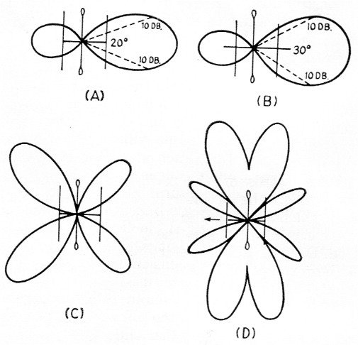
Fig. 1. Approximate field patterns of the "K4HWY Special" beam antenna for 20 meters (A), 15 meters (B), 10 meters (C), and 6 meters (D).
Multiband operation
The use of open-wire feeders fed from a standard antenna tuner permits feeding the beam on other bands without excessive losses in the line. S-meter checks with other hams at various distances indicate that the 15 meter pattern is essentially the same as on 20 meter (see Figs. lA and 1B). The 10 meter pattern (Fig. 1C) is a cloverleaf. The driven element works well as a dipole on 40 meter and the array does a good job even on 6 meter, four main lobes appearing off the ends of the beam as shown in Fig 1D.
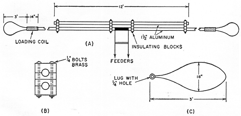
Fig. 2. Constructional details of the driven element - (A) the complete assembly, (B) the mounting insulator and (C) the "carpet beaters".
Construction
Fig. 2A shows a sketch of the driven element. A 12-foot section of 1½ inch aluminum tubing, insulated from and bridging the center portion, serves as a support. The supporting section is suspended from a triangular boom, using U bolts. The insulators between the driven element and the supporting section are in the form of clamping blocks. Each consists of four pieces of s-inch bakelite, 3 inches wide and 1% inches high, shaped to fit the aluminum tubing and clamped together with long h-inch stainless steel bolts.
Each of the loading coils is wound with 7 feet of 3/8 inch copper strip, turns spaced 1/8 inch. The form is a 14-inch length of bakelite tubing having an outside diameter of 1½ inches to fit into the end of the driven element which has an inside diameter of the same dimension. One-quarter inch stainless steel bolts are used to fasten the bakelite tubing- and aluminum tubing together and to anchor one end of the coil winding. Similar screws are used at the other end of the loading-coil form to anchor that end of the winding and for attaching the "carpet beaters." The latter are made of 6-foot lengths of 1/16 inch brass wire (No. 12 or 14 copper-clad is also suitable) bent into the form shown in Fig. 2C.
For a design frequency of 14,200 kc, the original length of the driven element was 33 feet 8 inches, including a 6 inch insulator at the center. Adding the loading coil and the "carpet beaters" increases the over all length to 42 feet. The director is 31 feet 6 inches long and is spaced 13 feet from the driven element. The reflector is 34 feet 11 inches long and is spaced 11 feet from the driven element. The boom is 24 feet long.
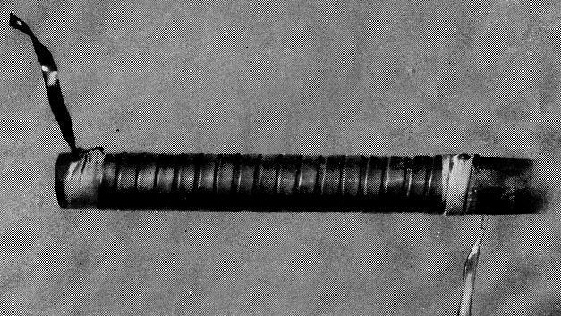
The low-capacitance loading coils are wound with copper strip on a bakelite-tubing form.
Fig. 3 shows the method used to keep the 600 ohm feeders clear of the tower for 360 degree rotation (180 degrees each side of the anchor point).
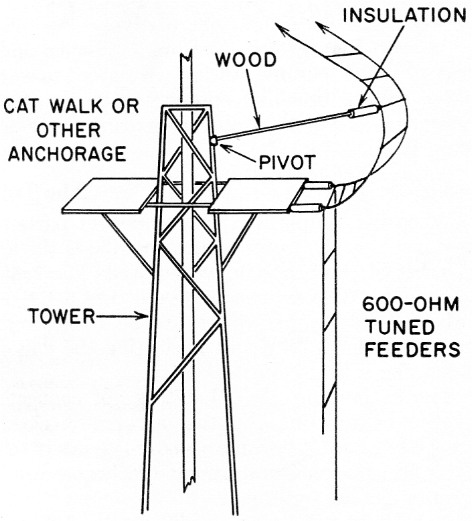
Fig. 3. Method used to hold the feed line away from the tower as the beam is rotated. The pivot at the tower should permit movement of the arm in all directions. Flexible insulated neon-sign wire (G-70-15) for the movable section of the line would simplify insulation.
Checks on the bandwidth were made using the AF67 loaded to a reference plate current of 100 ma. Over the range of 28,550 to 29,000 kc, the loading remained constant within 5 mA plus or minus. From 28,550 to 28,000 kc, the plate current gradually increased to 130 mA; from 29,000 to 29,700 kc, it gradually decreased to 92 mA. On 15 meters, the loading was flat across the entire band, within the 5 mA tolerance.
With the design frequency at 14,200 kc, the loading was flat within 5 mA plus or minus over the range of 14,140 to 14,300 kc; from 14,140 to 14,000 kc the plate current gradually increased to 125 mA. On 7 Mc, the current was constant within plus or minus 5 mA over the range of 7150 to 7300 kc, and gradually increased to 112 mA from 7150 to 7000 kc.(2)
Over the years, I've used just about every type of antenna - 8JKs, Lazy-Hs, bisquares, rhombics and Vees, but this tops them all.
Notes
- While it is doubtful that this objective is achieved in full, the characteristic current-distribution having a maximum either side of some minimum at the feed point should be evident. - Ed.
- Bandwidth will vary with feeder length. - Ed.
Charles H. Starn, K4HWY.