Bandswitching the mobile antenna
Remote system for 20, 15 and 10.
This bandswitching mobile antenna has an outward appearance no different from that of a conventional single-band center-loaded whip. A simple system of relays tunes the antenna for each band. Control and transmission lines are fed through the base section. Although designed especially for use with the KWM-1, it is easily adapted to any other type of installation.
A newly-acquired KWM-1 prompted a hasty search for a suitable mobile antenna for 20, 15 and 10 meter operation. Although there are several commercially manufactured three-band mobile antennas available, they are either trap antennas which do not make maximum use of the available whip length on all bands, or they are manually switched center-loaded affairs, which are quite efficient but inconvenient when changing bands. The best solution seemed to be a home-brew job using the band-change information available from the KWM-1 to operate relays that would automatically switch loading-coil taps when the KWM-1 was tuned up. This arrangement combines the high efficiency of the center-loaded whip with the convenience of the trap antenna.
An examination of the KWM-1 schematic shows a switch wafer ganged to the exciter-tune knob, which grounds Pin 15 of the power plug (J5) on 20 meters, Pin 16 on 15 meters and Pin 17 on ten meters. This switch is used to operate the relays for switching the loading-coil circuitry on the various bands. Twenty and fifteen meters are handled by changing taps on the loading coil. For ten meters, it is necessary to shorten the whip electrically. This is accomplished by switching in sufficient series capacitance to tune out the inductive reactance of the whip on this band. The arrangement is shown in Fig. 1. It may, of course, be applied to any installation by the substitution of a pair of s.p.s.t. toggle switches, or the equivalent in a rotary switch, for the KWM-1 control.
The antenna operates as a quarter-wave monopole with the automobile body as a counterpoise on all bands. An 8 foot whip is mounted on top of the loading coil, making the total length 9½ feet. By grounding the coax at the top of the base pipe, a closer impedance match to the RG-58A/U coax line is obtained. With the bottom end of the base pipe at ground potential, the arrangement offers a distinct mechanical advantage. The mounting can be made stiffer and more secure. Previous insulated systems have shown a tendency to short at the base insulator as well as being generally unsatisfactory mechanically. By using a piece of tubing for the base section, the relay-control wires and the antenna feedline may be run inside, resulting in a very neat-appearing installation. The various wires running through the base pipe assume the r.f. potential of the pipe. Therefore, by the time they reach the bottom end of the pipe, they are at ground potential and no bypassing or r.f. chokes are necessary in the control leads.
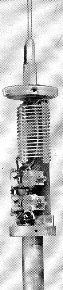
A three-band band-switching mobile antenna system. The switching relays and loading coil are mounted on an insulating strip between two circular end plates. Details will be found in the text.
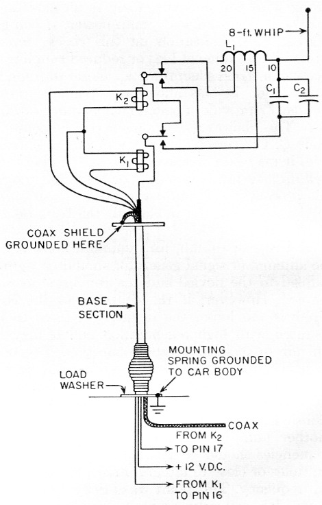
Fig. 1. Circuit of the three-band mobile antenna system. With both relays de-energized, as shown, the antenna is tuned for 20 meter operation. With Kt energized, the antenna is tuned to 15 meters and, with K2 energized, the system operates on 10 meters. Pin numbers refer to J5 on the Collins KWM-1. Ordinary switches may be used for control as discussed in the text.
| C1,C2 | Approximately 20 pF mica (see text). |
| K1,K2 | 6 or 12 volt d.c. antenna-switching relay (Potter & Brumfield KT11 D). |
| L1 | See text. |
The photographs show the details of construction. Epoxy impregnated glass fiber material was used where insulating material- is required because of its superior electrical and mechanical properties. Most of the larger cities have jobbers who deal in the various plastic materials, and it shouldn't be too difficult to locate the necessary tubing and sheet stock. In the event that it isn't readily available, a second choice would be fabric-base, Grade CE bakelite, although some loss in efficiency might occur with the poorer insulation.
All of the special fittings are simple but some of them would be rather difficult to turn out by hand. Therefore, it would be advisable to enlist the aid of a friend who owns a metal-turning lathe and a drill press, if possible.
Assembly
The assembly of the antenna is quite straightforward. Lockwashers should be used on all screws. Where plastic parts are held in compression by screws, it would be a good idea to put a drop of Glyptal or varnish over the threads of the screws as additional insurance against loosening.
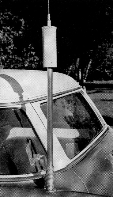
Base section mounting and loading-coil unit with weather shield in place.
Referring to the photographs, the top end plate of the coil enclosure is a 2¼ inch disk of 3/8 inch glass epoxy sheet, drilled at the center to pass a 3/8 inch bolt, and tapped at the edges for four 6-32 screws to fasten the tubular weather shield in place. This end plate is covered by a plastic drip cap to exclude rain. It is a lid from a 2½ inch plastic jar purchased at the local dime store. A 3/8 inch hole is cut at the center, and the lip is notched out to clear the weather-shield screws. The bottom end plate is a disk similar to the top end plate except that it is made of ½ inch aluminum. The center hole is drilled and tapped ½ - 24.
The two end plates are joined by a 6½ inch length of 1/8 inch epoxy glass sheet. This strip is used for mounting the loading coil and the switching relays. The edges should be beveled, and the width adjusted carefully to make a tight fit inside the coil, as shown in Fig. 2. The coil is a 16-turn section of No. 1206T Airdux inductor (No. 12 tinned wire, 1½ inch in diameter, 6 turns per inch). The taps should be set initially at 1¾ turns from the antenna end for 15 meters and at 11 turns for 20 meters. The 10 meter series-tuning capacitors and the coil taps should not be soldered permanently in place, since values may need changing in the final adjustment.
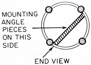
Fig. 2. Sketch showing how the edges of the coil-mounting strip are beveled to fit the inside diameter of the loading coil. The aluminum angle piece at each end of the strip should be placed on the left-hand side of the strip as indicated.
A 1_3/8 inch length of ¾ × ¾ × 1/16 inch aluminum angle is used at each end of the strip to join the strip and the end plates. The angle pieces are fastened to the strip using 6-32 screws and nuts. The screw holes in the strip side of the bottom angle piece should be slotted to permit adjusting the spacing of the end plates to make an accurate fit with the weather shield.
The upper end of the strip is fastened to the top end plate by a 3/8 - 24 stainless-steel bolt, 1_1/8 inches long, that passes upward through a hole in the angle piece, the center holes in the top end plate and the plastic drip cap, and a lock-washer, to a clamping nut. (It may be necessary to cut away a portion of the vertical side of the angle piece to clear the head of the bolt.) The clamping nut is made by drilling through and tapping 3/8 - 24 a 1_1/8 inch length of 5/8 inch stainless-steel hexagon rod. A standard 3/8 inch whip fitting threads into the upper portion of the nut.
The bottom angle piece is fastened to the aluminum end plate by two 6-32 machine screws tapped into the aluminum. The angle piece should be oriented so that its mounting screws do not interfere with the shield-mounting screws.
The base section of the antenna is an 18 inch length of 1 inch (i.d.) 0.062 inch wall aluminum tubing. Each end of this section is plugged with a 1 inch length of 1 inch aluminum rod drilled through, end to end, and tapped ½ - 24. Each plug is fastened in place with a pair of 3/16-inch 4-40 screws, diametrically spaced, passing through the wall of the tubing into tapped holes in the plugs.
The bottom plate of the coil mounting and the upper plug are fastened together by a threaded nipple. This nipple consists of a 1%-inch length of 3-inch stainless-steel tubing threaded 3 24. A similar nipple is used to join the bottom plug and the spring mount, and a third nipple is used to fasten the spring mount to the car body. If welding facilities are available, the bottom plug could be welded into the aluminum tubing, and the bottom end plate could be welded to the top end of the tubing as an alternative.
The cylindrical weather shield is a 7_3/8 inch length of glass epoxy tubing, having an inside diameter of 2¼ inches and a 1/16 inch wall. If the shield is to be painted, be sure that the pigment in the paint doesn't lower the Q of the coil. Krylon Dove Grey, No. 1605, has been found satisfactory. Other colors should be checked before using.
The spring mount for the antenna is a Master Mobile type 100-X which was modified to permit feeding the coax line and control wires through it. Both end inserts were drilled through and re-tapped for ½ - 24 threads. The drilling operation removes the internal jumper braid that shorts out the inductance of the spring. No trouble has been encountered to date because of the removal of the braid, but it would be a simple matter to replace it if found necessary.
The feedline and control wires should be fished through the base section before mounting the antenna on the car. I used RG-58A/U for the transmission line and No. 22 wire for the switching relays.
Mounting
The location of the antenna on the car is more or less a matter of individual choice. However, for maximum efficiency a location should be selected which keeps the loading-coil assembly at least 24 inches from the car body. Fender or trunk-lid mounting has proved to be very satisfactory. Because of counterpoise effects of the automobile body, the strongest signal will be in the direction which has the most car body between the antenna and the receiving station; i.e., if the antenna is mounted on the left rear fender, the strongest signal will be off the right front corner.
Mounting the antenna requires a ½ inch hole in the car body to clear the mounting nipple. To distribute the load of the antenna over an area, a large washer, at least 2 inches in diameter, should be used on the exterior side of the hole. If there is any curvature at the point where the hole is drilled, the washer should be shaped to fit the contour of the car body. A cardboard template is helpful in determining what shape to make the washer. It may also be advisable to use a large reinforcing plate around the hole, on the inner side of the car body, to prevent crimping of the body metal by the sway of the whip. Paint should be thoroughly removed from the area under the washer so a good contact with the car body will be obtained. A lockwasher should be used under the ½ - 24 nut that threads onto the mounting nipple fastening the mounting spring in place.
Tuning
Before tuning up, be sure that your car is parked in a clear area away from other cars and metal objects which could cause detuning.
An s.w.r. meter or reflectometer should be used for best results in tuning the antenna. With the unit completely assembled, except for the coil cover, fire up the rig on 10 meter and check the s.w.r. If it is more than the chart in Fig. 3 indicates it should be, select new values for C1 and C2 and try again. The 15 meter band is adjusted next by selecting the tap on L1 for lowest s.w.r. These results may be compared against the 15 meter curve in Fig. 3. The 20 meter band is adjusted last by again selecting the tap for lowest s.w.r. Replace the coil-assembly cover, recheck the s.w.r. on all bands, and you are ready to call "CQ DX." Excellent signal reports on all three bands have been obtained while using the KWM-1 and this antenna. The convenience of automatic bandswitching is especially enjoyable on a long trip where it is quite a nuisance to stop and change bands.
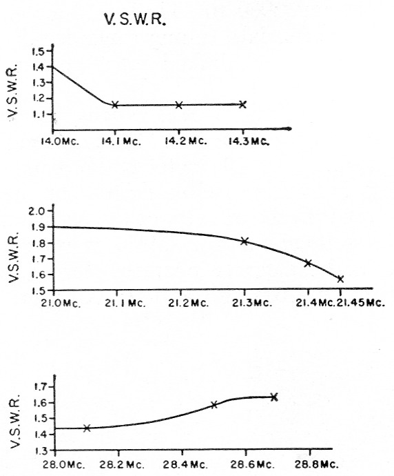
Fig. 3. Curves showing typical s.w.r. across the 20, 15 and 10 meter bands.
Shorter antenna
In the event that the 8 foot whip proves to be too long physically, it is possible to substitute a 6 foot whip by shorting out C1 and C2, and shifting the loading-coil taps to approximately 5_1/8 turns for 15 meters, and 15¼ turns for 20 meter it will be necessary, of course, to repeat the full tuning procedure if this is done. The shorter antenna will not beuite as efficient on 15 and 20 meter as the 8 foot whip, but excellent results have been obtained with it in spite, of its slightly lower efficiency. It might be well to mention that comparative tests showed an innense in radiated output of about 14 per cent when a brass whip was substituted for the original stainless-steel antenna. Therefore, it might be worthwhile to consider the use of lower-resistance whip material.E.A. Andrade, W0DAN.