Receiver input impedance matching
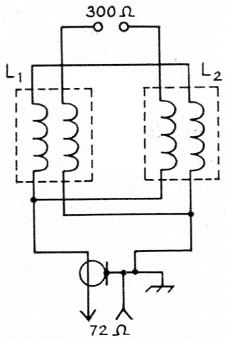
Fig. 1. Diagram showing connections when using TV front-end baluns for receiver impedance matching.
L1,L2 TV front-end balun coils.
After purchasing a new t.r. switch I realized it would be a problem to couple the switch to the receiver, since the receiver has a 300 ohm input and the switch has a low-impedance output.
Several methods of solving the problem were considered. I thought of using transmitting-type balun coils, building a matching device, or using antenna coils from an old junk-box receiver. It suddenly dawned on me that TV front-end tuners use a pair of balun coils to match a balanced 300 ohm line to a low-impedance unbalanced line. After purchasing a pair of these coils from a surplus store I installed them between the switch and receiver and found an increase in signal strength of at least two S units over the previously mismatched condition.
These balun coils are available from most surplus stores and measure about 3/8 × 1½ inch. They are bifilar-wound, one being a dark color and the other shiny in appearance. Close examination will identify the proper leads or an ohmmeter can be used to find the correct leads. The diagram in Fig. 1 shows the proper connections.
Clark A. Chamberlain, WSRSH.
The table below shows measured impedance at the 72 ohm side with a 330 ohm resistive load connected to the 300 ohm terminals. - Ed.
| Frequency (Mc) | Input Resistance (Ω) | Equivalent Shunt Capacity (pF)* |
|---|---|---|
| 7 | 100 | -86.5 |
| 14 | 90 | -.1 |
| 21 | 80 | +10.4 |
| 28 | 70 | +10.5 |
| 30 | 68 | +10.4 |
| 50 | 50 | +4.5 |
| 100 | 109 | -4.0 |
| 145 | 53 | +2.5 |
| 220 | 160 | -1.5 |
*Shunt capacitance required to be added (-) or subtracted (+) to resonate the circuit at the given frequency.