Voltage change nomograph for electromagnet coils
Those who like to rewind d.c. relays, solenoids, transformers, motors, or generators to operate on a new voltage and current will find the nomograph in Fig. 1 a time saver.
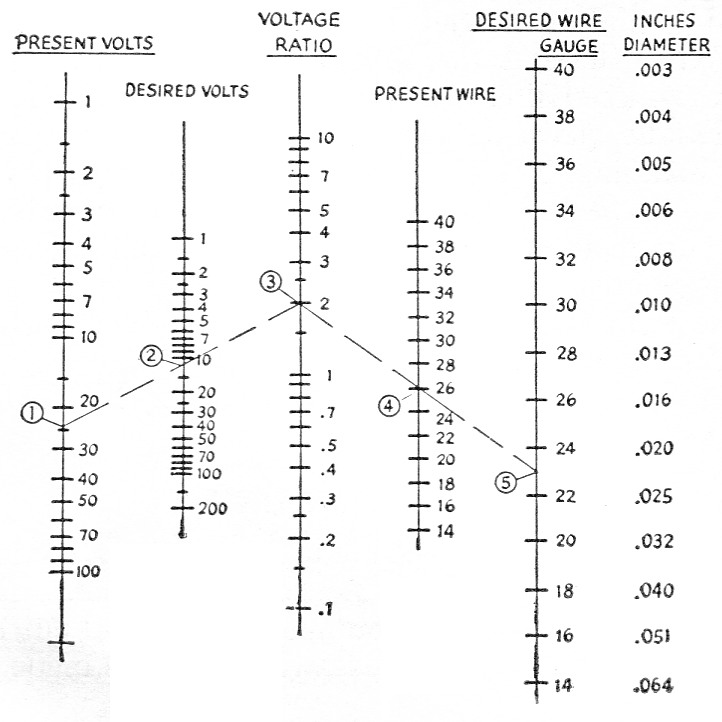
Fig. 1. Voltage change nomograph for electromagnetic coils.
The first three columns are for dividing the present operating voltage by the desired voltage. The right-hand three columns are for multiplying the cross-sectional area of the present wire by the voltage ratio to give cross-sectional area of the desired wire. By choice, the scales on the wire columns are given in AWG gauge and inches diameter rather than in cross-sectional area.
Example:
On hand -
24-volt relay wound with No. 26 wire.
Problem -
To find wire size to rewind relay for 12 volts.
Procedure-
1) Under present volts, mark 24 volts.
2) Under desired volts, mark 12 volts.
3) Draw line through 24 and 12 volts to ratio column.
4) Under present wire, mark No. 26 wire.
5) Draw line through ratio and No. 26 wire to desired wire column. Read No. 23 AWG gauge, or .023-inch diameter wire.
With this change in wire and voltage we get: one half the voltage, twice the current, one fourth the resistance, two times the cross-section area of wire and one half the turns (assuming same winding space filled).
Guy Buckner, W5VGK.