Coaxial cable attenuation
Some of the whys and wherefores.
That there are power losses in coaxial cable is well known, but just how those losses are distributed among the various parts of the cable is not-so-common knowledge. The variability of some of the factors is probably even less well known.
Coaxial cable attenuation can be attributed to two factors: basic losses in the cable components themselves, and the additional losses resulting from operating with an excessive standing-wave ratio. The ideal coaxial cable would consist of two highly polished, silver-plated copper tubes placed concentrically, using dry air as a dielectric material, with no variation in concentricity of the tubes. Such cable construction is obviously rather difficult to attain, and indeed can only be approximated in rigid applications.
For flexible applications, a precisely constructed cable utilizing a low-loss plastic material for a dielectric and braided copper wire for the outer conductor is the only satisfactory answer, and so most of our well-known coaxial cables are of this type.
Examination of Fig. 1 reveals that at 100 Mc. 80 per cent of the attenuation of a solid-dielectric cable using a low-loss dielectric such as polyethylene is due to copper loss in the center conductor. The remaining loss - approximately 20 per cent of the total attenuation - is divided between dielectric losses and copper losses in the outer conductor. As is obvious, at this and lower frequencies the center conductor more directly affects attenuation than any other cable component, and the design of low-attenuation coaxial cables revolves about this fact. Skin effect is no less evident in coax than in other h.f. or v.h.f. circuitry, and the surface of the center conductor should have as low r.f. resistance as possible.
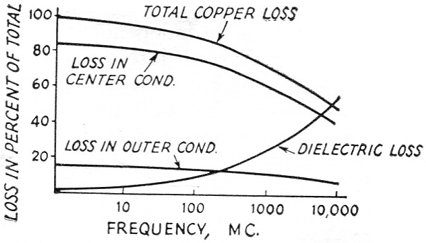
Fig. 1. Relative cable component losses vs. frequency.
Type RG-11/U, for instance, uses a stranded tinned copper center conductor. RG-11/U was designed for short runs or for inter-set coupling where ease of soldering was a prime factor. For transmission-line use, the 6.7 times greater resistivity of tin over bare copper results in greater attenuation, together with the use of a stranded instead of a solid center conductor. This attenuation increase (1.3 times) is a result of the spiralling effect of the r.f. current along the center conductor, coupled with the higher resistivity of the center conductor because of contact resistance between individual strands. JEL-104 is equivalent in every dimension to RG-11/U, but utilizes a solid copper-weld conductor.(1) Fig. 2 shows that the attenuation of JEL-104 is 16 per cent less than that of RG-11/U.
However, the size of the center conductor affects attenuation even more than the above factors. Compare the attenuation of RG-59/U and JEL-104 (Fig. 2), the former having a No. 22 center conductor and the latter having a No. 17 center conductor; the only factor here that has any significant effect on attenuation is the size of the center conductor. Obviously, if the size of the center conductor can be increased the attenuation will be decreased. Cable impedance, however, is dependent upon the ratio between the diameters of the inner and outer conductors, together with the dielectric constant of the dielectric material. The formula for determining the characteristic impedance of a coaxial cable is as follows:
![]()
where:
Zo = characteristic impedance
k = dielectric constant
D = diameter of dielectric (i.d. of outer conductor)
d = diameter of inner conductor.
Therefore, assuming the usual solid polyethylene as the dielectric material (k = 2.3), it is obvious that the size of the center conductor cannot be increased without changing the diameter ratio and consequently the impedance of the cable. If an increase in the over-all diameter of the cable can be tolerated, the size of the conductor can be increased, thus allowing an increase in d without changing the diameter ratio and impedance. Such an approach results, naturally, in logarithmically increased bulk and weight.
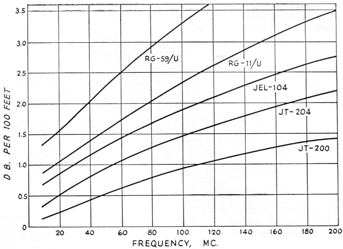
Fig. 2. Attenuation vs. frequency in several types of "75-ohm" cables. This graph gives comparison of cellular polyethylene (JT) and solid polyethylene (RG, JEL) dielectric coaxial cables.
Reducing the dielectric constant
A much better method is to decrease the dielectric constant of the dielectric material, thus allowing an increase in the size of the center conductor without necessitating a corresponding increase in the diameter of the outer conductor. Air has a dielectric constant of 1.0, and rigid cables using a center conductor supported by beads of insulating material to achieve a low dielectric constant have been used for purposes of low attenuation for years. Such constructions, however, are very expensive, besides requiring rigid support and the complicated plumbing necessary to insure pressurization to prevent moisture condensation.
Results similar to those obtained by the use of a gas-filled line can be attained with all the advantages of flexibility and lack of maintenance of the solid-dielectric cable by the use of cellular polyethylene as a dielectric material. Formed by means of a foaming agent intimately dispersed in the polyethylene granules before melting and extrusion, this material consists of a compact unicellular combination of polyethylene and air, each isolated air cell only a thousandth of an inch in diameter. The ratio of polyethylene to air is approximately one to one, with a resulting dielectric constant of 1.5.
Type JT-204 cable is equivalent to RG-11/U in all dimensions except conductor o.d., but utilizes a cellular polyethylene dielectric material permitting an impedance of 75 ohms with a No. 14 A.W.G. solid copper center conductor. RG11/U has a 7/26 A.W.G. stranded (approximately equivalent to No. 18) tinned copper center conductor, and at 100 Mc. exhibits an attenuation of 2.25 dB per 100 feet. The attenuation of JT-204 at 100 Mc is 1.5 dB per 100 feet, a decrease in attenuation of approximately 40 per cent as a result of the larger solid bare copper conductor. Times Wire & Cable type JT-200 is a 75 ohm cellular polyethylene dielectric cable with a jacket o.d. of 0.675 inch and a No. 10 A.W.G. solid copper conductor. As a result of the large conductor, JT-200 exhibits an attenuation of only 0.92 dB per 100 feet at 100 Mc.
Other benefits result from the use of cellular polyethyene - the weight of the cable is greatly decreased, and the tensile strength of the cable is increased (because of the larger center conductor).
Effect of impedance variations
Coaxial cable attenuation is also a function of v.s.w.r. in the cable itself. Cable with a certain nominal characteristic impedance does not exhibit the same impedance over the entire spectrum. Any eccentricity with respect to the location of the center conductor in the dielectric material results in a change in the effective diameter ratio and a consequent change in impedance. Cable core is manufactured by pulling the center conductor through the cross-head die of a thermoplastic extruder, which extrudes a continuous coating of dielectric material around the conductor. The polyethylene-covered conductor is then passed through a temperature-controlled water bath to cool the hot plastic material properly.
If eccentricity is combined with periodic variations in dielectric o.d. because of "surging" of the extrudate, discontinuities develop at frequencies at which the surges are one-quarter wavelength apart. These periodic resonances result in impedance variations of much greater magnitude than the variations resulting from eccentricity alone, and are coincident with sharp increases in attenuation at the resonant frequency. This phenomenon is present in all conventionally extruded cable. The degree of periodicity depends on manufacturing techniques.
It is possible to measure these impedance discontinuities with suitable equipment. Two techniques are used for production testing at Times Wire, one measuring frequency vs. impedance, and the other measuring frequency vs. attenuation. The first technique utilizes motor-driven variable-frequency oscillators, covering the range 0.5-250 Mc, mechanically coupled with a strip recorder. The output signal from the oscillator is fed to a voltage-divider network, the output of which changes as a function of the impedance of the network (cable sample) connected to it. The recorder is calibrated by establishing limits with known impedances. An a.g.c. feedback circuit is incorporated to insure a constant output voltage. Impedance variations appear as "grass" on the graph, with variations caused by periodic discontinuities appearing as high-amplitude spikes. The frequency at which an impedance discontinuity appears is immediately identifiable by reference to the frequency-calibrated base line of the recording. Although the theoretical impedance variation of RG cables in the 75 ohm class is ≈ 10 per cent, most standard RG cables so measured vary ≈5 to 10 ohms over the entire frequency range, with occasional periodic variations of 15-20 ohms or more, as shown in Fig. 3A.
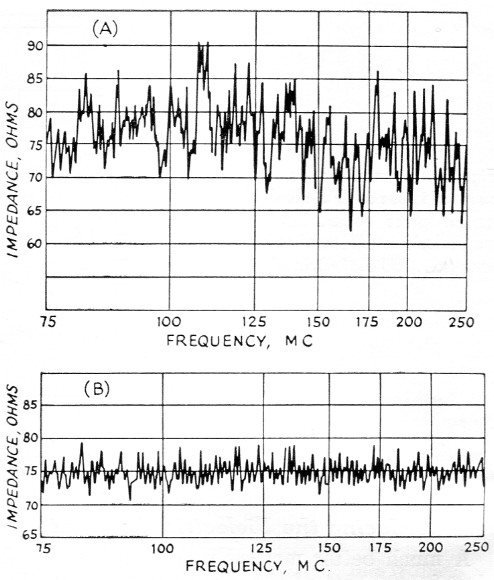
Fig. 3. (A) Variation of impedance with frequency in a length of standard RG-11/U cable. Note the high amplitude of variations, the impedance swinging = 10 ohm or more.
(B) Variations in pre-swept cables such as JT-204 are held within close limits.
Attenuation vs. frequency is measured by means of a visual display. The signal from a sweep generator covering the range 0.5-250 Mc is fed into one end of the cable under test. The output signal is amplified by a flat broad-band band-pass amplifier, rectified, and fed into the vertical plates of an oscilloscope through a calibrated attenuator. The sweep signal is displayed on the scope face as in Fig. 4 (50-250 Mc is the swing of the sweep generator in this case). The over-all attenuation characteristic, on a comparative basis, of the cable is now visible, and amounts to a total attenuation increase at the high end of the band of approximately 30 db. (cable sample consists of 1500 feet of RG-11/U). Attenuation suck-outs resulting from periodicity in the cable are evident at 75 and 175 Mc. The amplitude of the suck-out is determined with the calibrated attenuator, and the frequency is determined by means of a marker generator coupled to the broad-band amplifier. Suck-outs of 3 to 8 dB are quite common in standard RG cable, and 60 dB suck-outs have been observed in 30 dB of cable. In long runs, suck-outs can be disastrous if they occur at a critical frequency. By means of very close control of extrusion processes, coupled with 100 per cent sweep inspection of each reel of cable, the JT and JEL series cables are .held to impedance variations of t3 ohms (Fig. 3B) and are flat within 0.5 dB in 30 dB of cable.
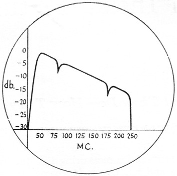
Fig. 4. Resonant periodicity in cable results in additional attenuation at frequencies at which a. quarter wavelength of the cable is resonant. This effect can be observed visually by means of the sweeping technique described in the text.
Resonant periodicity only becomes a problem above approximately 40 Mc, but impedance variations resulting from conductor eccentricity exist throughout the spectrum. As frequency increases, the v.s.w.r. of the cable limits its usefulness in application. As can be seen from Fig. 1, the dielectric material and braid become increasingly important above 150 Mc. The percentage of dielectric loss increases as a result of the increased power factor of dielectric materials at high frequencies. Resonant periodicity becomes more pronounced, but is relatively stable with physical movement of the cable in comparison with capacitance changes (with coincident impedance changes) resulting from flexure of the braid when operating at ultrahigh frequencies. As frequency increases to 5-10 Gc, relatively minor flexure of the cable results in large-order variations in attenuation. At 10 Gc 70 dB of cable may only be fifty feet in length, and variations of 10 or 12 dB can result from flexure.
These variations are primarily a result of the manner in which r.f. current flows along the inside of the braid. As frequency increases, the current tends to zigzag along individual wires, rather than follow the spiral of the braid. Because shield braid is made of many strands of wire in a basket-weave pattern, contact resistance at each crossover point contributes to the r.f. resistance of the outer conductor, and the greater the number of strands the greater the contact resistance. However, by suitable choice of braid angle (that angle the strands make with the longitudinal axis of the cable) and coverage, an increased number of strands can result in increased braid pressure and consequent decreased contact resistance at crossover points. The net result is that although contact resistance is theoretically increased by the additional strands, the actual contact resistance is decreased to a much greater degree by the greater braid pressure, the net result being a decrease in attenuation. The greater braid pressure also results in a more stable braid, with less change in attenuation with flexure. The application of a suitable tight jacket will also stabilize the braid configuration.
It is important to note at this time that losses resulting from excessive v.s.w.r. in coaxial cables are actually very small in comparison with the attenuation resulting from direct component losses. Excessive v.s.w.r. should primarily cause concern for the dielectric strength of the cable, since the maximum voltage in the line increases with the v.s.w.r. A glance at the attenuation vs. v.s.w.r. curves in the Handbook shows that v.s.w.r. must reach values in the order of 3:1 or 5:1 before appfeciable attenuation is apparent. Any additional attenuation resulting from v.s.w.r. is a function of the component attenuation already existing in the cable.
Jacket material
One more factor results in coaxial cable attenuation - contamination of the dielectric material by plasticizers used in the vinyl jacket. Most flexible coaxial cables use polyvinylchloride (vinyl) as a jacket over the braid to protect the cable from moisture, sunlight, and abrasion. Vinyl in its natural state is a very stiff material, which resists any flexing. In order to make vinyl pliable, or plastic, certain plasticizers are added to the vinyl compound. In the case of JAN cables such as RG-8/U, RG-11/U, RG-58/U, and RG-59/U, a non-resinous plasticizer is used. Upon exposure to the elements, particularly summer temperatures, the plasticizer leaches out of the vinyl and migrates into the polyethylene dielectric, contaminating it to the point where the dielectric constant and power factor are raised. As a result, the v.s.w.r. of the cable is increased, as is the attenuation. As a secondary result of the migration of the plasticizer out of the jacket, the vinyl becomes brittle and loses its pliability, with consequent cracks and breaks. The life of cables jacketed with contaminating types of vinyl is between three to seven years before contamination increases to the point where attenuation is extraordinary. The degree of contamination increases exponentially beyond this point, rising to very high values. One to two dB per hundred feet in RG-11/U at 30 Mc is a common attenuation increase after contamination has begun.
The above cable types and other RG cables using contaminating type jackets have been largely supplanted by cables electrically and dimensionally identical, but with non-contaminating type jackets. Cable types like RG-8A/U, RG-11A/U, RG-58B/U and RG-59A/U, for instance, utilize resinous plasticizers and offer life expectancies in excess of fifteen years. The price differential between cables using the two types of jackets is approximately one dollar per hundred feet.
High- molecular- weight carbon-black-loaded polyethylene(2) jackets such as Xelon contain no plasticizers of any nature, and offer life expectancies in excess of 25 years, in addition to being ten times less permeable to moisture than polyvinylchloride. For this reason, polyethylene jackets (which, incidentally, are usually specified for submarine cables) permit direct burial of coaxial cable.
I would like to thank Larry DeGeorge, W1ISV, for his invaluable assistance in preparing this paper, and also the Engineering Department of the Times Wire and Cable Company for the preparation of the graphs and charts used as illustrations.
Notes
- The JEL and JT type designations are those of the Times Wire and Cable Co., and indicate sweep-tested cables using solid and cellular polyethylene dielectric, respectively. These cable types are available through Times distributors in various parts of the country. Information concerning distribution can be obtained from the company at its homeoffice address, 358 H all Ave., Wallingford, Conn. - Ed.
- Not to be confused with dielectric polyethylene which does not stand up well as jacket material in outdoor service. - Editor.
Micheal Ferber, W1GKX.