Turnstile for two
A horizontally polarized omnidirectional mobile antenna.
Hey Mister! Do you have TV in your car?" This is the question usually asked when a bystander sees the turnstile antenna shown in the photograph. The antenna is not designed for TV reception, of course, but does perform as a nondirectional two-meter horizontally polarized antenna.
In mobile service, a horizontally polarized antenna has a considerable advantage over a vertical whip,(1) although the vertical is easier to mount. This advantage is especially marked when working with a horizontally polarized station over a line-of-sight circuit - and most fixed stations on two meters are horizontally polarized. Horizontal polarization helps reduce pickup of ignition noise from other cars - and from one's own car, too - since this type of noise tends to be vertically polarized.
A mobile antenna should have omnidirectional characteristics since its position will be constantly changing with respect to the station being worked. The turnstile has this feature.
What is a turnstile?
A turnstile is simply two ½-wave dipoles crossed at right angles to each other, with the two fed equal currents in 90 degree phase relationship. The resulting radiation pattern is practically a circle. Fig. 1 shows the pattern of a turnstile compared with that of a simple half-wave dipole. When the turnstile is mounted on a car the pattern will be modified somewhat but will remain generally omnidrectional.
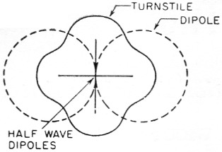
Fig. 1. Pattern of turnstile antenna (solid line) and simple dipole (dotted line).
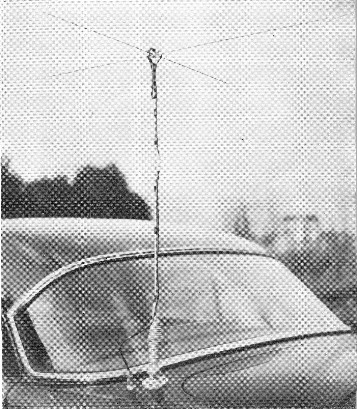
The turnstile mounted on the car body near the trunk lid. Electrical connections are made by means of a coaxial feed-through connector adjacent to the base mount.
A quarter-wave line section between the two dipoles is used for providing the 90-degree phase shift, as shown in Fig. 2. Since each dipole has an impedance of about 70 ohms, the quarter-wave section must have a characteristic impedance of the same value if the currents in both elements are to be equal. This results in a feed-point impedance of about 35 ohms.
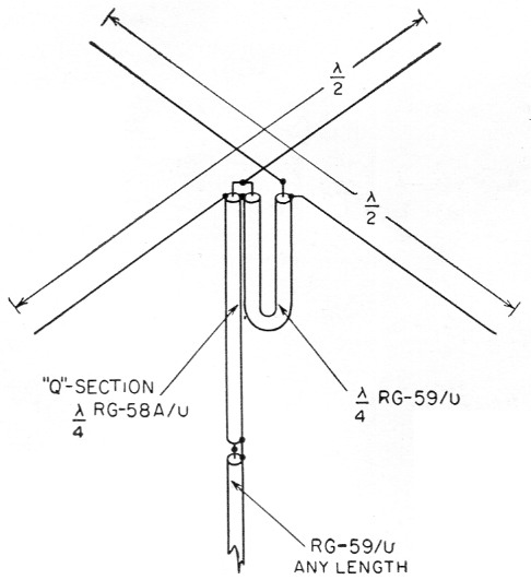
Fig. 2. Electrical connections of the turnstile. The length of each dipole is calculated by the usual formula: Length in inches = 5540/freq. (Mc). For 145 Mc the dipoles are 38¼ inches long. The phasing and Q sections are each 13½ inches for the same frequency.
Feeding the turnstile
It is desirable to transform the 35 ohm antenna impedance to a value that can be matched by available types of transmission line. For 73 ohm line, this transformation can be done easily with a quarter-wave impedance transformer or "Q" section. The required characteristic impedance of a matching section can be calculated from the formula:
![]()
where:
Z1 is the turnstile feed impedance and
Zo is the characteristic impedance of the transmission line.
Substituting 35 ohms for Z1 and 73 ohms for Zo (RG-59/U feed line) the required characteristic impedance of the "Q" section is very close to 50 ohms. Thus RG-58A/U cable can be used for the impedance transformer. A "70-ohm" line of any length can be used to feed the antenna through the "Q" section. Fig. 2 shows the electrical connections.
To calculate the physical length of the quarter-wave sections the following formula is used:
![]()
where:
f is the frequency in megacycles and
V is the velocity factor of the transmission line.
The velocity factor of both RG-59/U and RG-58A/U is 0.66, so a quarter-wave section for 145 Mc. will have a length of 13½ inches. Lengths for other frequencies may be found by substitution in the formula.
Mechanical details
Fig. 3 shows the mechanical details of the turnstile. The antenna may be considered to be made up of three major parts - the base, the supporting mast and the top sect'on. The latter includes the supporting hub and the elements.
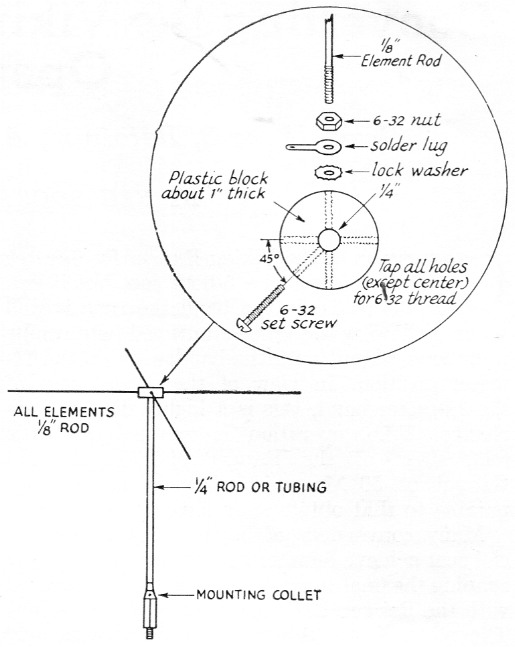
Fig. 3. Mechanical data for the turnstile antenna.
The supporting hub is a short cylinder cut from plastic rod. Polystyrene rod is available from most mail-order houses, but any type of low-loss plastic or Bakelite may be used. The hub should be at least 1 inch in diameter and about 1 inch thick. A %-inch hole is drilled through the center to fit over the 4-inch supporting mast. Five other holes are drilled as shown in Fig. 3 with a No. 36 drill, and then tapped for 6-32 threads.
The dipole elements are Vss-inch aluminum rods; these can be welding rods, usually obtainable in small quantities from local welding shops or suppliers. The antenna shown in the photograph uses M-inch rods of 2024-T4 (245-T4) aluminum, which were obtained from a local metal supplier. This type of rod is springy and hard enough to take a 6-32 thread.
Assembly of the turnstile involves the attachment of the elements to the hub along with the solder lugs, nuts and lock washers, as shown in Fig. 3. The rods should not penetrate the hub far enough to make contact with the mast. The assembly is slid over the mast and secured by tightening the 6-32 set screw. Then the electrical connections shown in Fig. 2 should be made. The junction between the 50-ohm "Q" section and 70-ohm feed line can be made conveniently by using the small BNC coaxial connectors. A type UG-89/U connector is used for the "Q" section and a type UG-260/U connector for the feed-line end.
A standard mounting collet, Ward type 89358, is used for the turnstile base. The collet comes with a ¼-inch hole in one end and a SAE stud on the other. The 3/8-inch thread is standard for mating with mobile spring-btise mounts. The collet has set screws for anchoring a %-inch rod in the hole. Other types of collets, with different hole sizes, are available. If one 0having the desired hole size is not obtainable the hole may be shimmed or enlarged to fit the diameter of the supporting mast.
Rod or tubing ¼ inch in diameter is strong enough to support the turnstile if it is mounted on the rear deck of the car as shown in the photograph. If bumper mounting is used, requiring a longer mast, a larger diameter should be used. Of course this means a larger hole will be needed in the collet and element hub.
A coax feed-through connector (Amphenol 83-1F) can be mounted beside the base mount to feed the transmission line through the car body, or the line can be routed under the car or through the trunk lid crack to the transmitter. The quarter-wave sections and feed line can be taped to the mast with Scotch electrical tape.
Experience has shown that it is best to mount the antenna on the driver's side of the car. This will reduce the chance of hitting low-hanging tree branches. A height of about 6% feet above ground is recommended. This is low enough to pass safely under most trees, underpasses, and toll gates but high enough to avoid knocking off a traffic policeman's hat!
Turnstile operation
Mobile operation with a turnstile antenna will be a pleasant experience for those who have been restricted to vertical polarization. Signals from other horizontally polarized stations will have less fading and flutter than before. Noise, the real demon of mobile operation, will be reduced to the extent that some of those weak ones can be copied. Practical tests have shown that the turnstile gives better over-all performance in mobile use than the horizontal halo antenna.
Turnstiles are not restricted to mobile operation. They make good omnidirectional fixed-station antennas, either singly or stacked at wavelength intervals. An installation of this type will make an excellent base-station antenna for civil defense groups.
Turnstiles can be constructed for other bands by substituting the appropriate frequencies in the formula for the quarter-wave line sections given earlier in the article. The regular formula for half-wave dipole length should be used for each turnstile element. However, horizontal antennas become impractical for mobile use on the lower frequencies because of their size.
One can judge for himself as to the ruggedness of the antenna. The one shown in the photo has had two years of mobile operation.
Notes
E. Laird Campbell, W1CUT.