Audio compression with transistors
Simple unit for improving A.M. and S.S.B. performance.
As the author points out, a compressor speech amplifier offers a means of E. g. increasing the average modulated output of a phone transmitter. The use of transistors in the unit described here provides compactness and simplicity impossible to approach with tubes.
The use of compressor amplifiers is not new. But for those who have never made their acquaintance, I will try to explain what they do and the advantages they offer.
Most of us are familiar with the oscilloscope picture of the normal voice signal which shows a characteristic with occasional high peaks, but a large portion of which is at relatively low amplitude. In fact, the average level is only about 30 per cent of the maximum peak value. However, if the modulation level is set so that the average value results in 100 per cent modulation, over-modulation will occur on the peaks. To avoid this, the modulation level has to be set so that 100 per cent modulation occurs only on the peaks, which means that most of the time modulation is far below 100 per cent. Since maximum output occurs only at 100 per cent modulation, it follows that the maximum output capability of the transmitter is utilized only a small percentage of the time.
More complete use of the modulated amplifier's capability can be realized if the lower-amplitude portions of the speech signal, which prevail most of the time, can be raised so as to modulate the transmitter output 100 per cent, at the same time reducing the amplitude of the occasional peaks so as not to overmodulate.
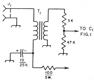
Fig. 1. Input circuit for carbon microphone. Capacitance is in µf.; resistance in ohms.
| J1 | Microphone connector. |
| T1 | Microphone transformer. |
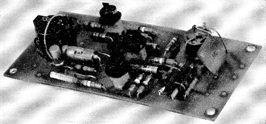
The components of the transistor audio compressor are assembled on a 2 × 4 inch printed-circuit board. T1 is at the left end, with CR1 and C2 slightly below and to the right. The transistors from top to bottom are Q1, Q2 and Q3. The clipper diodes, CR2 and CR3, are in the lower right-hand corner with the output connector above.
This is what the compressor amplifier does. It is essentially an audio amplifier with a.g.c. The stronger the input signal, the less the amplification will be. As a result, voice output from the transmitter is maximum most of the time rather than at only relatively infrequent intervals. Another advantage is that the operator does not have to be careful in holding his voice level constant, nor in the distance between his lips and the microphone. Without adjusting the level control, I can speak close to the microphone or back off as much as a foot without any variation in the peak power output or tripping of the voice-control relay. Operators who have voices with very little "talk power" will be especially benefited by using this device. Using the compressor is merely a matter of plugging the unit in between the microphone and the transmitter microphone jack.
Fig. 2 shows the circuit diagram of a compressor amplifier using transistors. The first and second transistors are conventional speech amplifiers with a nominal output of 0.1 volt. The output of the second stage drives the third transistor to saturation, producing a square wave output. This output is fed back through a 1:3 transformer, diode rectifier, and time-constant network to the input of the first stage. The diode rectifies the output of the third stage and applies it as d.c. bias to the base of the first transistor, changing its gain in proportion to the level of the output signal. The time constant of the RC network following the diode is selected to control the bias at a syllabic rate. The value of R1 sets the compression level. With a value of 2000 ohms, compression starts at 0.5 mv. and the output will hold constant within 3 dB of maximum over an input change of 20 dB.
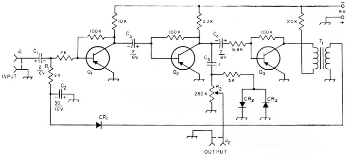
Fig. 2. Circuit of the transitorized compressor amplifier. Capacitances are in µF, resistances are in ohms, and fixed resistors are ½ watt.
| C1,C2,C3,C4 | Ultraminiature electrolytic. |
| C5 | Subminiature ceramic. |
| CR1 | SG-22 or 1 N138A silicon diode. |
| CR2,CR3 | 1N48 germanium diode. |
| J1,J2 | Microphone connector. |
| Ql,Q2,Q3 | 2N188A transistor (see text). |
| R1 | 2000 ohms, ½ watt (see text). |
| R2 | 250 kΩ potentiometer. |
| T1 | Subminiature 1:3 interstage transformer. |
The two diodes, CR2 and CR3, and the 5K resistor R2 form a clipper circuit that clips transient peaks by about 2 dB. Harmonic distortion at full output is 1 per cent from 300 cyles to 20,000 cycles. The attack time is 0.05 second, which is fast enough for good s.s.b. operation.
Construction
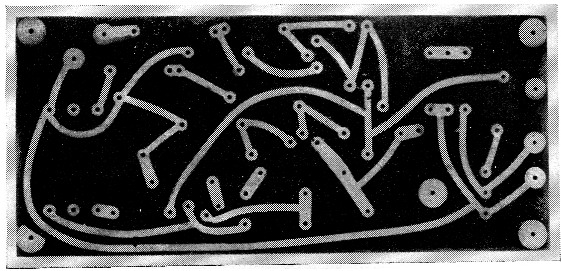
Bottom view of the printed-circuit board before mounting components. The upper edge of the board in this view corresponds to the lower edge in the preceding top-view photograph. Conventional wiring may be substituted.
A unit of this type lends itself well to printed circuitry,(1) although conventional wiring may be substituted, of course. The amplifier is assembled on a board of epoxy material measuring 2 by 4 inches that will fit inside a 5 × 2¼ × 2¼ inch Minibox, along with the dry battery that powers the unit. The arrangement of components and the etched wiring pattern are shown in the photographs. Placement of parts is not highly critical. The transistor sockets are Cinch-Jones, or similar. Other components are of the subminiature or ultraminiature type.
Transistor units having a beta factor of 20 or more should be selected.(2) The type 2N188A is recommended, but some 2N107s, 2N109s or 2N188s will show sufficient gain.
The unit will operate indefinitely from a 9 volt transistor battery having a diameter of about 1 inch and a length of less than 2 inches, such as the RCA V300, Burgess P6 or Eveready 226.
This unit can be used in other applications employing a microphone and audio system. When used with a p.a. system, it is no longer necessary to ride the gain control to compensate the difference in levels of a band and a vocalist, or to worry about audio feedback if someone screams into the microphone.
Notes
- See Middleton & Stueber, "12AX7 Modulator unit utilizing printed circuit techniques," QST, May, 1958.
- Priebe, "Checking transistors," QST, April, 1958.
Edward Arvonio, W3LYP.