Simplified break-in control
Receiver muting and side tone without relays.
This break-in system for blocked-grid keying systems makes use of the receiver's a.v.c. system for muting. Only a single dual triode, in addition to the t.r. switch, is required. In many cases, operating voltages can be taken from the transmitter. dispensing with the separate supply.
The author has long been interested in the advantages of c.w. break-in and, for about two years, had used a form of semi-break-in in which the v.f.o. and antenna relay were turned on with the first dot and held in for several seconds. The use of three relays in this circuit left much to be desired, however, as anyone who has ever tried operating with many relays banging and humming can attest.
The purchase of a new Heathkit Apache transmitter offered the possibility for a new control circuit, and it was decided to design and build same posthaste.
Several ideas had to be kept in mind in the design of this unit, which were as follows:
- Utilization of the timed-sequence grid-block keying system supplied in the transmitter which, by the way, performed excellently.
- No relays!
- Electronic silencing of the receiver.
- Electronic antenna change-over.
- Ability to hear the transmitted signal in the receiver at reduced and variable gain.
- Audio-tone keying monitor, independent of transmitter or receiver controls.
Circuit
A look at the diagram of Fig. 1 will reveal that the circuit has three sections. The power supply is a bit unusual, because the center tap of the transformer is not grounded. The supply provides -105 volt for the muting and side-tone circuits and +105 volt for a t.r. switch. Back-to-back filament transformers with two half-wave selenium-rectifier power supplies could have been used instead, but all the parts in this circuit were on hand. It might be possible to "steal" the voltages from some existing piece of gear, but the negative voltage should be regulated to stabilize the bias circuits.
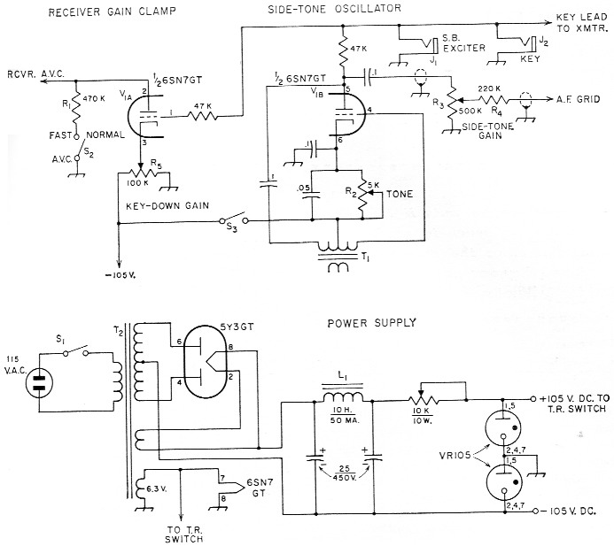
Fig. 1. Diagram showing receiver-muter, side-tone oscillator and power-supply circuits of W4HBO's simplified break-in system.
Capacitances are in µf. Capacitors with polarity markings are electrolytic. Other capacitors are 400 volt paper.
Resistances are in ohms and resistors are ½ watt unless indicated otherwise.
| J1,J2 | Open-circuit key jack. |
| L1 | Filter choke. |
| R1 | Muting-bias resistor. |
| R2 | 5 kΩ potentiometer. |
| R3 | 500 kΩ volume control. |
| R4 | 220 kΩ. |
| R5 | 100 kΩ potentiometer. |
| S1,S2 | S.p.s.t. toggle switch. |
| S3 | S.p.s.t. switch ganged to side-tcne gain control. |
| T1 | Push-pull audio-output to voice-coil transformer, secondary not used. |
| T2 | Power transformer: 500 v.c.t., 40 mA; 5 V, 2 A; 6.3 V, 2 A (Thordarson 22R00 or similar). |
| V1 | 6SN7GT or equivalent. |
V1A is the receiver gain clamp. The negative keying voltage on its grid keeps it cut off with the key up. Closing the key grounds the grid at the same time that the transmitter is keyed. This allows the tube to conduct, and the negative drop across RI is applied to the receiver a.v.c. line. The key-up voltage on Pin 3 (cathode) should be about 20 volts positive measured from Pin 1 (grid). If the keying voltage is too small, the tube will not cut off, and the receiver will be silenced all of the time. Moving the tap on the 100K potentiometer toward ground until the cathode is about 20 volts positive from the grid will correct this. (Note: It is obvious, of course, that this circuit can be used only in gridblock-keyed transmitters.)
V1B is a side-tone oscillator. It is keyed in the plate circuit. The 220K resistor R4 isolates the circuit from the audio grid in the receiver so that when the side-tone gain is turned down the receiver audio is not short-circuited to ground. The frequency of the side-tone oscillator can be changed by adjustment of the 5000-ohm potentiometer Re in the cathode circuit. The tone can also be altered by changing the capacitance in shunt with R3.
Antenna change-over is accomplished by an electronic t.r. switch. The actual circuit was taken from QST,(1) and since many good circuits have been described in the last year or so, the t.r. switch will not be discussed here.
Construction
Construction is nct critical, as long as the audio is kept away from the power supply. It is quite conceivable that room could be available to construct the unit right inside the transmitter, obtaining power from the transmitter power supplies.
It is desirable, however, to build the t.r. switch in a separate shielded box of some kind, and to filter the leads coming from it to prevent harmonic radiation.
Installation
The installation of the unit is quickly accomplished as follows:
- Plug the key lead from the unit into the transmitter key jack.
- Connect the wire marked "Receiver A.V.C." in the schematic to some point on the receiver a.v.c. line. A good place is at the a.v.c. switch, if the receiver has one.(2)
- Connect the shielded wire marked "A.F. Grid" to the grid terminal of the audio output stage in the receiver, and ground the braid.
- Plug the power cord into a 110 v. a.c. socket.
- Since the power cable from the t.r. switch was made plug-in for convenience, plug this into its socket.
- Connect the various coaxial cables to their appropriate connectors on the t.r. switch.
- Plug the key into the key jack in the unit.
While the receiver is out of its case to connect the a.v.c. and audio leads, it will be a good idea to install a coax connector for the antenna lead if one is not already present. This will shield the receiver input so that less transmitter signal can get into it.
It will also be a good idea to test the unit before reinstalling the receiver. If it is not possible to cut the receiver off entirely with this unit, as was the case here, it is possible that one of the i.f. stages is not on a.v.c., and if its grid lead resistor is lifted from ground and connected to the a.v.c. line, the problem should be solved.
Operation
The operation is extremely simple. To hear your own signal, adjust the key-down gain for desired volume. For off-frequency operation, or if it is desired to have just an audio tone, turn the key-down gain control for minimum gain, and turn up the side-tone gain to the desired side-tone level. The 470K resistor, R1, should be in the circuit for c.w. to speed receiver recovery, but should be switched out of the circuit for proper a.v.c. action on a.m.
The jack marked "S.B. Exciter" is to allow the transmitter keying lead from a single-sideband exciter to be plugged in in parallel with the key. This control unit may be used to silence the receiver on s.s.b. as well as c.w. through this jack, and if the keying circuit in the transmitter is keyed on a.m. also, the unit may be used on a.m.
This unit has now been in use for several months, including the 1958 Sweepstakes contest, when it really proved itself. With an average junk box and a few good friends to help donate parts, the unit here, including t.r. switch, was built for about $5 to $10, most of which went into the t.r. switch. If all the parts were purchased new, it could probably be built for about $25 or less, and it sure is worth it!
Notes
- Arvonio, "An electronic transmitter-receiver antenna switch," QST, October, 1957.
- In some receivers, the a.v.c. system is disabled by grounding the a.v.c. line. Thus the a.v.c. switch must be in the open or "a.v.c." position for the muter circuit to function. Since this leaves the receiver's a.v.c. system in functioning condition, a second pole on the a.v.c. switch, disconnecting the a.v.c. line from the a.v.c. rectifier, will be required if a.v.c. disabling for c.w. reception is desired. - Ed.
Jerome H. Horwitz, W4HBO.