An 800 Watt P.E.P. input linear
7094s in parallel.
Because of its low driving-voltage requirements, the 7094 lends itself well to resistive broad-band input circuits. As a result, good stability can be obtamed with circuit simplicity.
Here is an 800 watt linear amplifier that takes advantage of the high power sensitivity of the new RCA 7094 beam power tubes. It is about as simple as a two-tube high-power amplifier can be, since there is no tuned input circuit, and no neutralization. It is stable and free of parasitics on all bands from 80 to 10 meters.
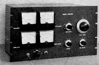
A clean-looking 800 watt linear amplifier. The band switch and pi-network controls are at the right. Shielding enclosure is of perforated aluminum. The panel is a standard 10½-inch rack unit.
The circuit diagram, Fig. 1, shows an input circuit consisting of a 50 ohm 50 watt Globar resistor. A noninductive resistor with a rating of less than 50 watts can be used because less than 40 watts peak is needed to develop the required driving voltage for full peak output, Class AB1. With c.w. and single-sideband voice waveforms the average dissipation is very much less. If a Globar or noninductive resistor can't be located, eight or ten two-watt carbon resistors in series parallel would probably do the trick.
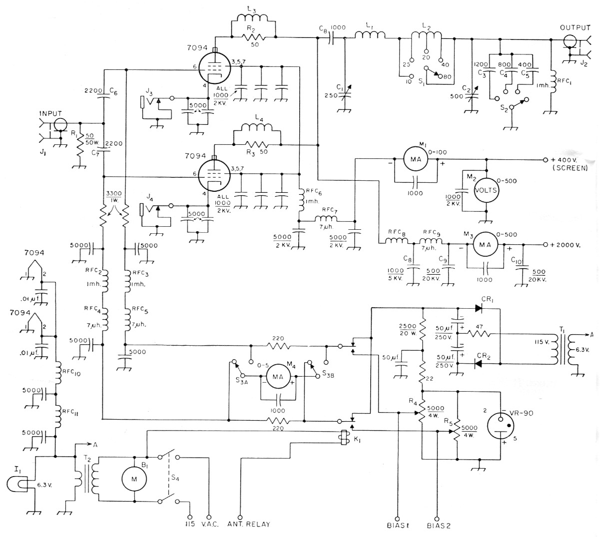
Fig. 1. Circuit of the 800-watt linear amplifier. Unless otherwise indicated, capacitances are in µµf. All fixed capacitors except those marked with polarity and those listed below are disk ceramic. Resistances are in ohms, and resistors are ½ watt unless indicated otherwise.
| B1 | Blower, 15 c.f.m. or more (Surplus, Burstein-Applebee etc.) |
| C1 | 250 pF 3000 volt variable (Johnson 154-9). |
| C2 | 500 pF 2000 volt variable (Johnson 154-3). |
| C3,C4,C5 | 2500 volt mica. |
| C6,C7 | Mica. |
| C8 | 5000 volt ceramic (Centralab 858S-1000). |
| C9,C10 | 20,000 volt ceramic (Centralab TV-207 or equivalent). |
| CR1,CR2 | 100 mA selenium rectifier. |
| I1 | 6.3 volt panel lamp. |
| J1,J2 | Coax receptacle (S0-239). |
| J3,J4 | Closed-circuit phone jack. |
| K1 | D.p.d.t. 115 V a.c. relay. |
| L1 | 4 turns 3/16 × 1/16 inch copper strip, 1_3/8 inch diameter, 2½ inch long (part of B&W 851 coil unit). |
| L2 | 4¾ turns No. 8, 2¾ inch diam., 1¾ inch long, tapped at 1¾ turns from L1 end, plus 9½ turns No. 12, 2¾ inch diam., 1½ inch long, tapped 7 turns from output end; see text (Part of B&W 851 unit). |
| L3,L4 | 3 turns No. 12, 3/8 inch diam., 1 inch long. |
| M1,M2,M3,M4 | 3½ inch square meter (Simpson Model 1327). |
| R1 | Noninductive resistor; see text. |
| R2,R3 | Three 150 ohm 1 watt carbon resistors in parallel. |
| R4,R5 | 5 kΩ 4 watt wire-wound potentiometer (Mallory M5MPK). |
| RFC1,RFC2,RFC3, RFC6 | 1 mH r.f. choke (National R-50 or similar). |
| RFC4,RFC5,RFC7,RFC9 | 7 µH v.h.f. choke (Ohmite Z-50). |
| RFC8 | 145 µH r.f. choke (National R-175A). |
| RFC10,RFC11 | 20 turns No. 14, 3/8 inch diam. |
| S1 | Heavy-duty band switch (part of B&W 851 unit). |
| S2 | 4 position single-pole ceramic rotary switch (see text). |
| S3 | D.p.d.t. rotary switch. |
| S4 | D.p.s.t. toggle switch. |
| T1 | 6.3 V 3 A filament transformer (Stancor P-6466 or similar). |
| T2 | 6.3 V 10 A filament transformer (Stancor P-6308 or similar). |
The 50 ohm resistive input does three important things. It matches the output impedance of many of the new s.s.b. exciters, and simplifies coupling problems; it eliminates any need for grid tuning, and so speeds up band changing; and it loads the grid circuit so heavily that the amplifier is extremely stable. This last is particularly important with tubes of high power sensitivity. Because of this low resistance and heavy loading, the usually desirable neutralization can be omitted.
A reversed 3-ampere 6.3-volt filament transformer, T1, and voltage-doubler circuit supply 250 volts for standby cut-off bias and for operation of the VR-90 voltage-regulator tube for regulated operating bias. A small d.p.d.t. relay, K1, seen on the corner of the chassis in the top and rear views, can be actuated by the exciter VOX relay or, as in the author's case, from extra contacts on the coax antenna relay. Energizing this relay connects each grid to its own potentiometer arm on separate 5K potentiometers R4 and R5. Connections are run from these potentiometer arms to terminal-block positions 1 and 2 so bias can be checked with an external voltmeter after the shielding is all in place. The screwdriver shafts of the two bias pots can be seen just above the terminal board in the rear view.
At the rear of the chassis are the two cathode jacks J3 and J4 which permit individual metering of the two tubes. The bias pots should be adjusted so that each tube idles at 30 mA. The individual settings in this case were -63 volt and -68 volt.
The 5 mA grid meter can be placed in the grid circuit of either tube by means of a d.p.d.t. switch, S3. It should be left in the grid of the tube with the lowest bias. If the needle even flicks on modulation it is a sure sign that the amplifier. is being overdriven, and is out of the AB1 operating region.
The rest of the r.f. circuit is a conventional pi network. The two variables are Johnson 250E30 (154-9) and 500E20 (154-3) with 0.075- and 0.045-inch spacings, respectively. The coil is a B&W 851 with four turns removed from the 80-meter section, and the 40-meter tap moved one turn toward the h.f. end. This gives the right Q for operation at 2000 volts and 400-ma. peak. The coarse loading switch was taken from a TU-9-B tuning unit, so there is no problem in handling the high tank currents. This pi net has worked into some awkward antenna inputs with standing-wave ratios as high as 6:1.
The plate choke is a National R-175A. The metal mounting bracket was removed so that the top cover would clear the top end of the choke. The blocking capacitor is a type Centralab 858. The parasitic chokes consist of three turns of No. 12, 3/8 inch in diameter and one inch long with three 150 ohm 1 watt resistors in parallel soldered across the three turns. The tube sockets are mounted 5/8 inch below the surface of the chassis, according to the manufacturer's instructions for best shielding of the input and output circuits.
The chassis measures 3 by 12 by 17 inches and the panel is 10% inches high. The top of the chassis is divided in half by an aluminum partition shield so that the meters and filament transformer will not be subjected to the r.f. field. The bottom of the chassis likewise has a shield across the middle. All leads passing through this shield are heavily bypassed and filtered. The "hot" half of the bottom is further divided by another shield which separates the output loading capacitor from the area of the tube socket, grid, and filament leads. All screen-grid terminals are individually bypassed with 1 nF 2 kV disk ceramics.
A blower at the rear of the chassis provides ventilation for the tubes. The one shown is a surplus item which the author happened to have. It is probably larger than necessary. Instead of one large hole for the blower exhaust, a series of %-inch holes is drilled in the edge of the chassis to provide better r.f. screening. The grid-circuit swamping resistors are located near the blower exhaust so that they will be in the air stream.
It is a bit of a luxury to have four meters, but they do dress up the appearance, and balance the panel. The 500 mA plate meter is, of course, an absolute must. The 5 mA grid meter is not strictly essential, but was added as an overdrive indicator. The other two meters are a 500 volt d.c. meter for the screen voltage, and a 100 mA meter for the screen current. At W8GRY the screen supply is a voltage-regulated variable-voltage unit, so the voltmeter serves a purpose. The screen-current meter is advisable because mistuning with high gm tubes can easily result in excessive screen dissipation.
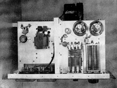
In the upper right photograph, the fixed and variable pi-network output capacitors are in the lower right-hand section, shielded from tube sockets and grid-circuit components to the left and bias-supply circuit above.
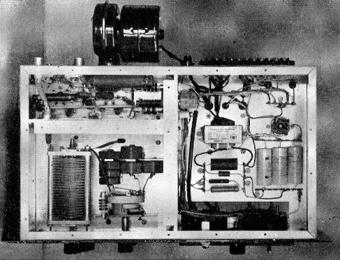
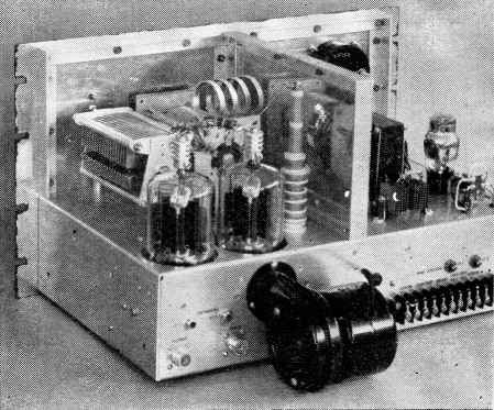
In the photograph in the center, 12 × 17 × 13 inch chassis provides plenty of space for the components of the 800 watt linear amplifier without crowding. Power and r.f. circuits are isolated by a partition shield. A cutout in the right-hand side of the chassis provides clearance for the meters. The transformer at the left is T2.
The bottom photograph is a rear view of the 800 watt linear showing terminal arrangement and mounting of the blower. Aluminum angle provides support for the shielding enclosure.
An advantage of this resistive-input amplifier over grounded grid amplifiers should be pointed out. In the grounded-grid circuit, the final and the exciter are essentially in series, with the result that tuning or loading the final affects the loading adjustments of the exciter. With this amplifier, exciter adjustments and final adjustments are completely independent. The low drive requirements of the 7094 tubes make it practical to use a 50 ohm resistive input which, in turn, makes for a simple circuit of good stability and maximum ease of tuning.
Edward B. Noel, W8GRY.