Station control circuits
Tying the transmitter, receiver and antenna together.
Here are some station control circuits that result in getting on and off the air "easily and quietly." They are in use in a voice-controlled kw. s.s.b. rig (sometimes operated on c.w. or a.m.). While you may not want to use the over-all circuit verbatim, some of the basic ideas might well fit into your rig.Figure 1 shows a version of blocked grid keying. With all three power supplies shown turned on and switch S1 open, the screen grid goes to cathode potential through R1 (about 25,000 ohm), and the sum of the screen pack, plus the bias pack, is applied to the control grid as negative bias. The tube is completely cut off and becomes inoperative. As the tube is drawing no current, the plate power supply sees only its bleeder resistor. The power supply must be properly designed to have good regulation with no external load, or its voltage will soar when the transmitter is in the stand-by condition.
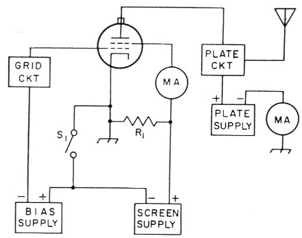
Fig. 1. In this switching circuit, opening Si brings the screen grid to ground potential thrcugh R1 and raises the control grid to the sum of the bias and screen supplies.
When S1 is closed, R1 becomes part of the bleeder on the screen supply, and the bias and screen supplies perform their jobs independently. Proper adjustment of these two supplies sets the operating point of the amplifier. The switch Si has to handle only the current through R1 plus any screen current, and it can be the voice-controlled relay contacts.
Fig. 2 is a satisfactory variation of Fig. 1 if the combined screen-bias supply is heavily bled through R2 and R3. About 100 mA bleed is satisfactory. The 40 µF capacitor is necessary to ensure a low audio impedance of the operating bias supply if grid current is drawn, and is in addition to the filter in the supply. A similar capacitor across R1 might be a good idea but has not been tried yet.
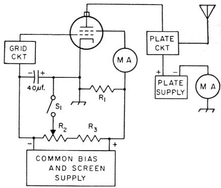
Fig. 2. The bias and screen supplies can be combined if a heavy bleed resistor (R2 and R3) is used. A high capacitance across RI might improve the linearity of the amplifier.
Fig. 3 shows an electronic transmit-receive switch of the cathode-follower type using the well-known principle of a high value of grid leak to block itself off when a powerful signal (such as the station transmitter) hits it. This type of circuit has been reported by some users to generate TVI by acting as an overdriven amplifier. Putting the low-pass filter between the t.r. switch and antenna takes care of the TVI problem, however.
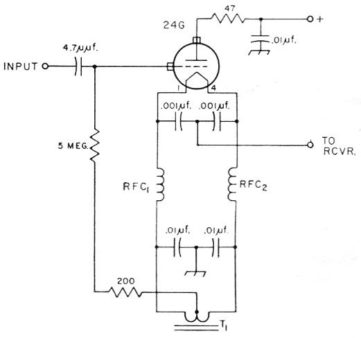
Fig. 3. A high-powered version of the cathode-follower t.r. switch.
Fig. 4 is the t.r. switch of Fig. 3 with the previous transmitter control. When the amplifier is on standby (S1 open) the plate circuit of the amplifier becomes the input circuit of the t.r. switch. This steps up the impedance of the 50-ohm transmission line of the antenna to a high impedance for the grid of the t.r. cathode follower. This transformer action gives a voltage gain to the t.r. switch. At this time the blocked final amplifier is inoperative and therefore does not load the tank circuit as it would in systems where the amplifier is allowed to draw idling plate current during standby periods. Blocking the amplifier also eliminates the diode noise that would otherwise mask weak signals.
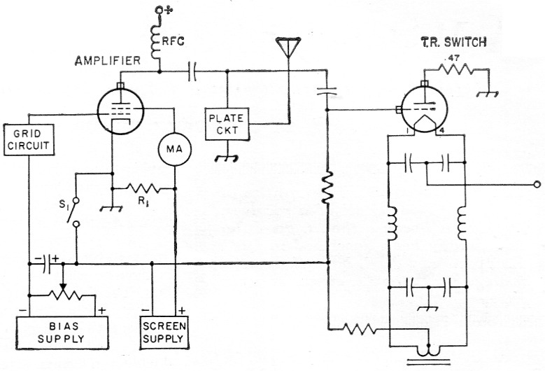
Fig. 4. Combining the t.r. switch with the amplifier switching circuit. Grounding the d.c. circuit of the t.r. switch through Si lets the screen supply serve as the t.r. switch supply during reception. Insulation in T1 should exceed screen supply voltage.
When S1 is open, the t.r. tube gets anode voltage from the screen supply through R1, one end of which is on ground. On transmit, this voltage is shorted out by S1, resulting in no anode voltage for the t.r. switch.
This t.r. switch has been used as shown in Fig. 4 very satisfactorily with no damage to the receiver from a 1-kw. amplifier. However, there is a small capacitive feedthrough from the amplifier to the output of the t.r. switch. Therefore, the well-known grounded-grid type t.r. switch of Fig. 5 was also put into service, after the cathode follower switch.
The 6AB4 grounded-grid t.r. switch was built directly into the receiver and uses the receiver power supply. This t.r. switch by itself has been used with low-power rigs with no damage to the receiver or TV set.
The circuit of Fig. 4 and the additional t.r. switch of Fig. 5 (built in the receiver) have been in use for some time with completely satisfactory results. The switch Si is not manually operated; it is a circuit on the voice-operated relay of the exciter. The back contact on this same circuit is used to turn on the receiver, via the so-called "stand-by switch" circuit of the receiver. The circuit allows getting off and on the air without the bang of relays (assuming the sensitive voice-operated relay is quiet), allows for fast breaks, and yet it completely protects the receiver. Some receivers click badly when switched to stand-by or back on. This should be corrected, as the click can cause unstable voice-controlled operation by triggering the rig via the microphone.
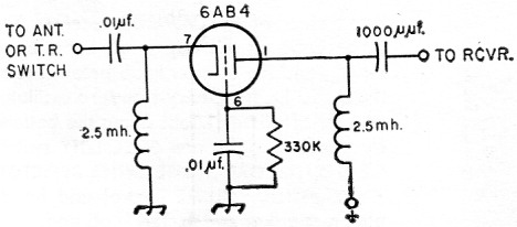
Fig. 5. Additional protection can be obtained by building this t.r. switch into the receiver. In low-power applications, it can be connected to the antenna feedline.
There is a gain of about two S-units in the 24G cathode follower. With the plate and screen voltage off, there is enough feedthrough from antenna to receiver through the 24G to receive satisfactorily by increasing the receiver gain control. You can also peak the final plate tank with or without the final being on and without excitation to the final by listening in the receiver.
The high-resistance grid leak must be a high-voltage type, or several smaller resistors in series, as it will see a peak r.f. voltage nearly equal to the plate volts of the final amplifier. This high voltage is why a tube like the 24G was selected, as its grid-to-filament breakdown voltage is very high. The 5 pF coupling capacitor to the grid of the 24G is a Jennings vacuum type X-5.
The filament chokes in the 24G were wound self-supporting, 15 turns of No. 14 enamel wire, 34-inch diameter. The heater chokes (not shown) for the 6AB4 were wound of No. 20 enamel wire, 15 turns, ¾ inch diameter.
This voice-controlled system has also been used very satisfactorily on a.m. I often wonder why voice control is not used more on a.m., as it increases the operating pleasure a great deal. One of the big advantages of s.s.b.-type operation is that VOX is customarily used. This need not be limited only to s.s.b.
The latest change in the circuit of this article occurred when a 0-100 microammeter was placed in series with the bottom end of the 24G t.r. tube grid leak. This meter then read 24G grid current and worked very well as a plate tuning meter for the final. Grid current ran about 100 microamperes for a kw. input to the amplifier. I found that the grid leak had to be a low-capacity type or it would burn up. The successful resistor was a 5 megohm deposited-carbon high-voltage type.
Paul Barton, W6JAT.