High-power triode amplifiers for 50 Mc
Improved tank circuits using standard plumbing components.
When W4UCH unwrapped his triode amplifiers in the ARRL Lab recently there were mixed reactions on the part of the bystanders. Newcomers to the game hardly recognized the tubes. Triodes - in a transmitter? But oldtimers looked long and lovingly at those beautiful big bottles and that wonderfully straightforward circuitry. Nostalgic sighs echoed around the place for days.
But these 50 Mc amplifiers are no anachronisms. The author makes a very good case for them in v.h.f. service. With surprisingly moderate drive, they deliver a clean signal as fat as the law allows - and they do it with an over-all economy and simplicity hard to equal with tetrodes.
When the 50 Mc band is open for FZ-layer or sporadic-E DX, just about anything in the way of a transmitter will work out well, if it is used on a good antenna system. When a signal is running 60 dB or so above the noise level of the receiver, another 10 to 20 dB is not going to make a great practical difference in communication, unless there is severe interference from other signals on the same or closely adjacent frequencies. Six-meter men have long since ceased to be surprised when fellows 2500 miles away all but block their receivers with Gonset Communicators.
But after the band closes down the low-power enthusiast is back working locals most of the time, and his reliable radius seldom exceeds much more than 50 miles. Too many of these fellows do not realize that they are missing much of interest that the 6-meter band has to offer. Though it has been demonstrated time and again, most amateurs still do not believe that reliable 50-Mc. communication is possible over distances up to 400 miles or so on phone, and as much as 1200 miles on c.w., when an efficient transmitter in the medium- or high-power brackets is employed.
The writer's hobby within a hobby has been for the past few years, working extended-range "groundwave" contacts on 50 Mc phone. Regular and reliable work has been done with K2RRG, 20 miles northwest of New York City, in Upper Saddle River, N. J., and W3BWU, Pittsburgh, Pa. Other stations worked frequently on a.m. phone include W8SSD and W8CMS in Ohio, W2YYI, upstate New York, W1CLH, Connecticut, W1FOS, near Boston, and many others in Delaware, New Jersey, Pennsylvania, Connecticut and the Long Island area. It should be emphasized that this is consistent coverage, over a period of three years, so such results cannot be attributed to unusual conditions.
A fairly good antenna is a "must" for this sort of thing. A 4-over-4 is used here, and most of the other stations mentioned used stacked allgigii of about this size, or larger. Very high power is not absolutely necessary, though it is helpful. Some of the stations listed above run no more than 200 watts or so, but most are in the high-power bracket.
At W4UCH the emphasis has been on efficient triode amplifiers for transmitting. High-power triodes may be out of fashion for work on lower frequencies, but we believe that they have many advantages for use at 50 Mc. and higher. Particularly when efficient tank circuits are used, they work with a degree of over-all efficiency that is hard to equal and well-nigh impossible to beat with any of the tetrode or pentode tubes so commonly used in today's amateur transmitters.
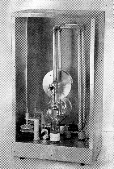
The W4UCH 50-Mc. amplifier with its front cover removed. This is the "small" model using 100THs.
Look over the performance table given herewith for a good idea of what a well-designed push-pull triode amplifier has to offer at 50 Mc. Also, the simplicity of the power supply required, compared to the devices needed with tetrodes of the same power level, is worthy of note. We feel that the amplifiers shown here get to the kilowatt level as simply and effectively as any that can be built today. If simplicity is, as we believe it to be, the epitome of good engineering, these amplifiers take the prize.
Design features
A look at the schematic diagram will show that there is nothing new circuitwise about these amplifiers. They are exactly like the push-pull cross-neutralized triode jobs that were standard equipment in amateur transmitters on all frequencies, before the days of tetrodes. Only one feature departs from customary design practice, and that is the use of M-inch copper tubing in the plate tank circuit. The plate circuit design was evolved in 1956, when several months were spent in work on various tank circuits. This size and shape resulted in the highest Q that is practical for a balanced tank circuit capable of handling a kilowatt input at 50 Mc.
A high-Q tank circuit such as this has advantages other than that of high efficiency. Because of its extremely high Q, it will not pass on the higher-frequency components present in the drive from the preceding exciter unit, which so often cause TVI in more conventional but less selective amplifiers. Result: a very low TVI potential.
The crossover neutralization eliminates any possibility of positive feedback through the tubes, a common source of trouble in tetrode amplifiers, even when they appear to be neutralized. A good test of true neutralization and component layout is to run full voltage on the amplifier and tune the grid and plate circuits throughout their entire ranges with no drive applied. Even when no bias is applied to the grids there should be no tendency to oscillation at any point. These amplifiers can be run at a full kilowatt input on a.m. phone at the writer's location in a TV fringe area, without any TVI. This is possible even with the shielding removed.
Construction
Most of the constructional features are visible in the photographs, and dimensions are given for those who may wish to build their own. Two basic amplifiers have been used. One employs a pair of 100THs, and the larger uses 450THs or TLs. As they are essentially the same physical size, 750TL and 1000 T tubes may be used, as well as the Westinghouse 6C21s shown in the photograph of the larger amplifier. Unless you have these tubes on hand, or can get them economically, there is little justification for use of anything larger than the 450s, at amateur power levels.
The plate tank circuit is made of ½ inch copper tubing. Right-angle bends are accomplished by the use of standard plumbing components. The plate-power end of the line is mounted on a 500 pF high-voltage TV standoff. The power is fed through two r.f. chokes, the common connection of which is bypassed by a similar capacitor, for effective decoupling of the power lead.
Heat-dissipating connectors made especially for this application are used. The front one has a tapped hole to pass a 5/16 inch screw for turning the movable capacitor plate. The tuning capacitor is a disk type, with plates 4 inches in diameter.(1)
The chassis of the 100TH amplifier is 7 by 11 by 2 inches aluminum. A cabinet of sheet aluminum can be made very readily. The only ventilation needed is provided by a 4-inch screened hole in the front panel, at a point adjacent to the large portion of the tube envelope. The top of the case can be perforated aluminum or screening. No forced-air cooling is required.
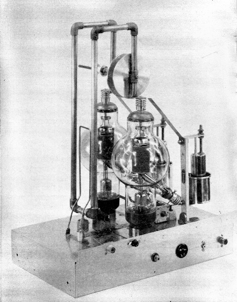
The larger model uses 450TL or higher-dissipation triodes of similar dimensions. Tubes shown are Westinghouse 6C21s.
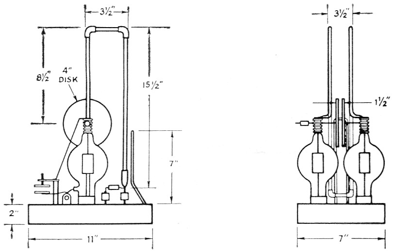
Fig. 1. Principal dimensions of the 100TH amplifier for 50 Mc. Copper tubing and right-angle fittings arestandard plumbing items.
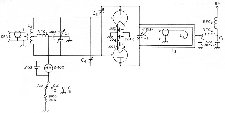
Fig. 2. Schematic diagram and parts information for the W4UCH triode amplifier using 100THs.
| C1 | 30 pF per-section split-statorvariable (Hammarlund HFD-30X). |
| C2 | Variable capacitor made from 4 inch disks; see photos and text. |
| C3,C4 | Disk-type neutralizing capacitor, 1-11 pF (Bud NC-853) |
| C5 | 20 µF 450 volt electrolytic. |
| C6,C7 | 500 pF 20 kV TV type bypass. |
| L1 | 2 t. No. 14 enamel, 1¼ inch diam. |
| L2 | 3 t. each side of center, No. 14 enamel, 1½ inch diam. Space turns so C1 tunes near middle of range. |
| L3 | Plate line; see Fig. 1 and text. |
| L4 | Output coupling loop; see Fig. 1 and text. |
| RFC1,2,3 | Solenoid v.h.f. choke, 26 t. No. 22 enam. on ½ inch poly rod or tubing. |
Power supplies
Not the least of the advantages of these amplifiers is the simplicity of the power-supply setup required. A dual high-voltage supply is recommended by the writer for handling the modulator and amplifier. With a Variac connected in the a.c. line to the primaries of the two plate transformers, the power level can be varied from 50 to 1000 watt, while retaining reasonable balance between the modulator power output and the amplifier input. It is pointless to run a kilowatt to work someone across town, when just a few watts will do exactly as well. In fact, it will be found that a high percentage of all 50 Mc hamming can be done readily enough with moderate or even low power. It is nice to be able to increase power quickly to the maximum that the law allows, however, and continuously variable control of the a.c. input voltage to the plate transformers makes this possible with a twist of the wrist.
| Class C, Phone or C.W. | ||||
|---|---|---|---|---|
| Plate voltage V | Plate current mA | Driving Power W | Input W | Output W |
| 3000 | 333 | 20 | 1000 | 750 |
| 2000 | 500 | 30 | 1000 | 735 |
| 1500 | 400 | 15 | 600 | 420 |
| 1000 | 300 | 15 | 300 | 200 |
| 800 | 200 | 8 | 160 | 100 |
| Class B S.S.B. Linear, Peak Envelope Values | ||||
| 3000 | 600 | 12 | 1800 | 1000 |
| 2600 | 600 | 16 | 1200 | 630 |
| 1500 | 475 | 17 | 713 | 355 |
| 1000 | 340 | 6 | 340 | 195 |
| 800 | 280 | 5 | 283 | 149 |
The output coupling link should be adjusted for optimum loading at the highest plate voltage that is to be run Somewhat tighter coupling will be needed to attain highest possible efficiency at lower plate voltages, but maximum efficiency is not an important consideration in Class C service except at the highest power levels. Proper loading for linear operation is more critical and careful adjustment of the coupling should be made for each plate voltage change, when the amplifier is being used as a linear.
Notes
- These parts, the heat-dissipating connectors and the neutralizing capacitors (as well as the complete amplifiers), are available in kit form from Richcraft Engineering Co. at moderate cost, if desired.
Robert M. Richardson, W4UCH.