Ferroelectric capacitors
An application in an F.M. capacity-modulated V.F.O.
Although the voltage-sensitive capacitors described in this article are a few years old, they have had little or no application in amateur equipment. Here's an opportunity to get acquainted with their characteristics. A practical application in frequency-modulating a v.f.o. is shown, and there could hardly be a simpler way of getting on f.m.!
Frequency modulation of a variable-frequency oscillator (v.f.o.) may be achieved by varying any of the elements of the frequency-determining resonant circuit in proportion to the modulation signal.
An inexpensive and easily varied circuit element is the capacitance. By using recently developed ferroelectric capacitors(1),(2) in a properly designed circuit it is possible to achieve good frequency stability at low cost with adequate deviation for f.m. at the fundamental of the oscillator with modulation voltages of the order of 50 volts. Besides telephony, those amateurs interested in code, teletype, or facsimile can use frequency modulation in a frequency-shift system.
The physical size of two ferroelectric capacitors is shown in Fig. 1 in comparison with a 1 watt resistor, a diode capacitor, and a scale. The University of Michigan experimental capacitor has an initial capacitance of approximately 260 pF and can be reduced to about 25 pF with the application of 300 volts bias. The "Mucon" capacitor, a commercially available unit, has an initial capacitance of approximately 400 pF and is reduced to about 100 pF with 300 volts bias.
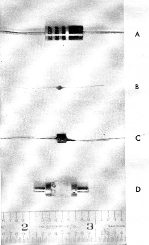
Fig. 1. Typical sizes of ferroelectric capacitcrs.
(A) 1 watt resistor.
(B) University of Michigan ferroelectric capacitor (200 pF)
(C) commercially available ferroelectric capacitor (400 pF)
(D) diffused silicon nonlinear capacitor diode (2 pF).
This article briefly presents the basic design theory and the description of a v.f.o. that is modulated by the University of Michigan ferro-electric capacitor.(3)
Theoretical circuit design considerations
Ferroelectric materials are found to have a dielectric constant that is a function of the applied electric field (bias) and temperature. For a typical capacitor fabricated from a wafer 0.005 inch thick and approximately 0.02 × 0.02 inch square operated at 39 °C, the variation of capacitance as a function of applied bias voltage is shown in Fig. 2. For this same capacitor biased at 150 volts the capacitance vs. temperature is shown in Fig. 3.
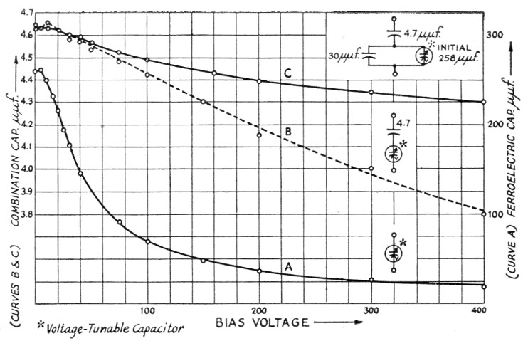
Fig. 2. Capacitance vs. voltage for typical experimental U. of M. capacitor.
(A) Ferro-electric capacitor;
(B) ferroelectric capacitor in series with a silver mica;
(C) ferroelectric in series with a silver mica and shunted by a silver mica.
Ferro-electric operating temperature 25 degrees C.
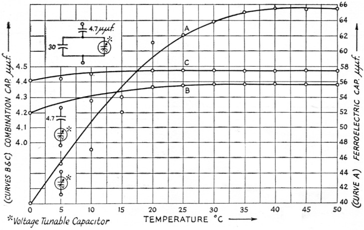
Fig. 3. Capacitance vs. temperature for typical experimental U. of M. capacitor.
(A) Ferroelectric capacitor;
(B) ferroelectric capacitor in series with a silver mica;
(C) ferro-electric in series with a silver mica and shunted by a silver mica.
Ferroelectric biased at 125 volts.
By biasing the ferroelectric capacitor to a middle value and adding to the bias a modulation signal it is possible to get a capacitance variation that is a monotonic function of the modulation signal. If this capacitor is then placed in the resonant circuit of an oscillator, an f.m. modulator is obtained (see Fig. 4A).
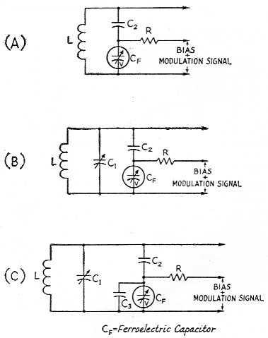
Fig. 4. (A) Basic tuned circuit for an f.m. oscillator.
(B) Tuned circuit for an f.m. oscillator to achieve high stability.
(C) F.m. oscillator tuned cirtuit for multiband operation. C3 is used to reduce the deviation when operating at harmonics of the oscillator frequency.
If C2 is large compared to CF then the resonant frequency is determined by CF and L. In this case large changes in frequency are possible, on the order of 3 to 1. This large change will result either from a voltage or temperature change; thus, this circuit would give very poor temperature stability. However, it should be noted that such a large degree of voltage tuning is not required for f.m., although this configuration could be used by putting the ferroelectric capacitor in a thermostatically controlled crystal oven and using a d.c. bias voltage for center frequency tuning and applying a very small signal for modulation. Of course, the 3-to-1 tuning range is still excessive and should be reduced. For some amateurs this might be experimentally interesting. For those amateurs interested in modifying present v.f.o.'s a different approach should be used.
V.f.o. center frequency stability is a principal design interest. The required percentage change in capacitance of the resonant circuit is small because the percent change in frequency is small. For instance, for narrow-band f.m. at 4 Mc, L and C might be 20 µH and 80 pF, respectively. To achieve a 3 kc deviation would only require C to change by 0.12 pF.
The circuit Fig. of 4B will give the desired deviation with the minimum temperature dependence when C2 is properly selected. (Here tuning is done with C1.) To achieve this result Cr. should be modulated so that a maximum capacitance change. is obtained that is reasonably linear. For a typical capacitor this may be a change of 50 pF.(4) Now this large change in capacitance must be reduced to a smaller change across C1. This is done by making C2 small. Curves B in Figs. 2 and 3 are for typical series combinations of C2 and CF. Consider CF to have a capacitance of 62 pF when biased at 125 volts. From Fig. 3 it is seen that for a 50 degree C. change in temperature the capacitance varies about 26 pF. Thus, if the v.f.o. was designed to give 3 kc deviation for a change of 50 pF in CF this temperature change would only result in a 1.6 kc shift of the center frequency. Normal temperature changes will be much less.
Capacitor C2 serves three purposes: (1) it provides a high impedance to ground for both the bias and modulation voltages; (2) it reduces the change in capacitance CF to a smaller value across L and C1; and (3) it multiplies the effective Q of the circuit. If the Q of C2 is large the Q of C2 and CF in series is approximated by
![]()
where
Qv is the Q of CF.
If CF is very much larger than C2, as it is in the practical case, the effective Q of the circuit is greatly improved. This is important since the Q of commercial ferroelectrics may not be too good.
When the same v.f.o. is used for multiband operation it is necessary to change the deviation in order to maintain a constant deviation from band to band. This is most easily achieved circuitwise by switching in additional padding capacitance across CF (as in Fig. 4C). Curves C of Figs. 2 and 3 show typical characteristics for this case.
Practical circuit design considerations
To demonstrate the feasibility of n.f.m. a typical commercially available all-band v.f.o. (Heath-kit VF-1) was modified as shown in Fig. 5 and the accompanying photographs. The basic circuit is the series-tuned Colpitts or "Clapp" oscillator circuit. The tank circuit consists of two separate coils and two separate stator connections of a ganged capacitor to develop the basic output frequencies. The basic output frequency in range 1 is 1.75 Mc., doubling to 3.5 Mc., and quadrupling to 7 Mc, while the basic output frequency in range 2 is 7 Mc, doubling to 14 Mc, tripling to 21 Mc, and quadrupling to 28 Mc. Padder capacitors are placed in parallel with the sections of the ganged tuning capacitor for adjustment. Following the discussion above, a series arrangement consisting of a 7.5 pF silver mica capacitor and a 200 pF ferroelectric capacitor are connected across range 1 of the tank circuit while a second series arrangement consisting of a 3.7 pF NPO capacitor and a 200 pF ferroelectric capacitor are connected across range 2 of the tank circuit. According to FCC regulations the channel width for n.f.m. should not exceed twice the highest audio frequency in the modulating signal; therefore, based on an upper audio limit of 3 kc., the channel width should not exceed 6 kc. In band-switching operation the modulation index is multiplied by the same factor that the carrier frequency is multiplied by. Therefore, if the basic output frequency is 7 Mc, for example, with a frequency deviation of 2 kc, the output at 28 Mc. (i.e., the fourth harmonic of the basic output frequency) will have a deviation of 8 kc., which is far too great. In order to maintain a constant deviation for a given modulation voltage, additional padding is switched across the ferroelectric capacitor as the band is switched to higher frequencies. Since n.f.m. is not allowed in the 1.75 Mc band, the basic output frequency was considered to be 3.5 Mc and the deviation adjusted at this point to be approximately ± 2 kc for a change in bias of ± 40 volt. For 7 Mc operation a 30 pF padder, C5, is switched across the ferroelectric capacitor as shown in the schematic. With this arrangement deviation in the 1.75 Mc band would be one-half of the deviation obtained in the 3.5 Mc band, or about ± 1 kc. The basic output frequency in range 2 is 7 Mc. and the deviation is adjusted at this point to about ± 2 kc. for a change in bias of ± 40 volts. For operation at 14, 21, and 28 Mc additional padding capacitance is switched across the ferroelectric as shown.
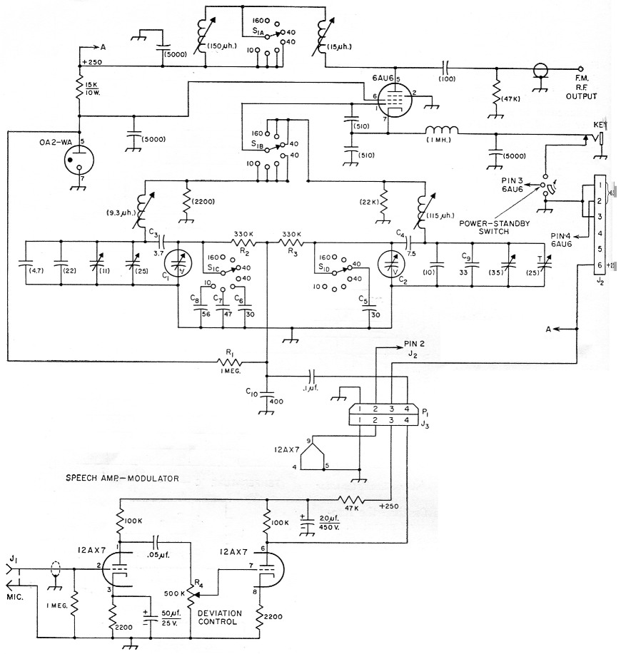
Fig. 5. Circuit for commercial v.f.o. kit modified for f.m. This circuit uses U. of M. experimental ferroelectric capacitors, but commercially available capacitors may be used with only slight changes. Capacitances are in pF unless otherwise indicated; capacitors with polarities marked are electrolytic. Resistors are''/ watt. Values in parentheses are unchanged from the original v.f.o. circuit.
| Cl,C2 | Ferroelectric capacitors, 200 pF initial capacitance. |
| C3 | Ceramic NPO (1.5 and 2.2 pF in parallel). |
| C4 | Silver mica (two 15 pF units in series). |
| C5-C9 | inc. Silver mica. |
| C10 | Mica. |
| J1 | Microphone connector, chassis mounting. |
| J2 | 6 prong cable connector, male (Jones P-306-CCT). |
| J3 | 4 prong chassis connector, male (Jones P-304-FP). |
| P1 | 4 prong cable connector, female (Jones S-304-CCT). |
| R1,R2,R3 | Composition, ½ watt. |
| R4 | 500 kΩ control, audio taper. |
| S1 | 4 pole, 7 position ceramic rotary |
Note: 11 meter position in original v.f.o. circuit eliminated.
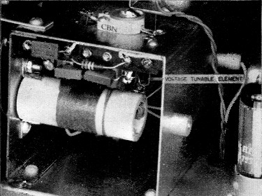
Mounting of the ferroelectric modulating capacitor. One circuit layout precaution should be taken: the lead from C2 to L and Ci (Fig. 4C) should be short and mechanically rigid. Other leads are not too critical.
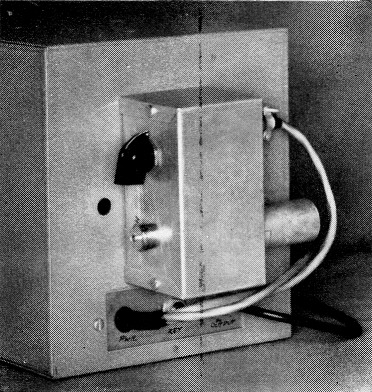
Outboard location of the modulation amplifier.
The ferroelectric capacitor bias voltage is 150 volts and is taken from the plate of the 0A2-WA regulator tube. Decoupling of the r.f. and a.f. signals from the bias is obtained by means of the 1-megohm resistor, R1. Capacitor C10, and R2 with C1 or R3 with C2 and other parallel capacitors limit the high-frequency response of the modulator. The principal components that decouple the two r.f. tank circuits and decouple the r.f. from the audio amplifier are R2, R3 and C10. When constructing this portion of the circuit it is important to keep all leads short and rigid at the junction of R2 with C1 and R3 with C2. Note that C9 is 33 pF instead of the 47 pF used in the Heathkit VF-1.
The modulator section is a two-stage audio amplifier utilizing a 12AX7 in a straightforward circuit. The gain control, R4, at the input to the second audio section, serves as a deviation control. Since the amplitude variations at the plate of the audio amplifier determine the deviation of the oscillator, controlling the input signal to the audio amplifier also controls the deviation of the oscillator. The optimum setting of this control will vary somewhat from band to band and is best determined by operational checks. The final setting should correspond to a deviation of somewhat less than 3 kc.
The modulator was constructed in a 2¼ × 2¼ × 4¼ inch Minibox and mounted outboard fashion on the rear of the v.f.o. Audio leads were brought into the v.f o. through shielded cables.
Since this particular v.f.o utilizes two tuned circuits in order to obtain band spread, it was necessary to replace the existing band switch with a four-section, seven-position, nonshorting type of ceramic switch. In most v.f.o. modifications, where the tank is a single tuned circuit, band-switch modifications will be much simpler. In any event, all modifications can be made by following the ideas presented in earlier sections.
Recalibration of the v.f.o. should follow standard procedures as outlined in most radio handbooks.
Performance characteristics
The oscillator frequency deviation on each band was measured by using a frequency counter 3n conjunction with a stable frequency source. The d.c. bias on the ferroelectric capacitor was varied 40 volts either side of the 150-volt bias level and the deviation noted. Two sample curves are shown in Fig 6. Fig. 6A demonstrates the deviation where the fundamental and operating frequencies are the same, in this case 7.2 Mc. Fig. 6B shows the deviation at the fourth harmonic of the fundamental frequency, or 28.8 Mc. Note that the modulation index in the two ranges is almost identical and that the. modulator is linear over the entire range. The deviation is within allowable limits on all bands from 3.5 through 30 Mc.
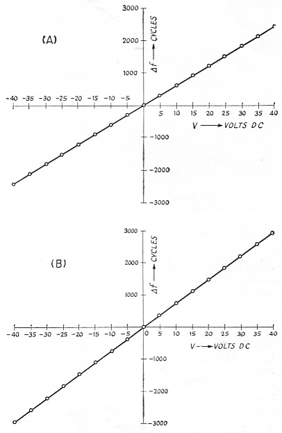
Fig. 6. (A) Measured deviation for the f.m. v.f.o. (fo = 7.2 Mc).
(B) Measured deviation at 28.8 Mc. (set on 10 meter switch position).
D.c. voltage shown is the change in volt from the initial bias of 150 volts.
The temperature stabilities of the v.f.o. with and without the ferroelectrics in the circuit are compared in Fig. 7. The degradation of the v.f.o. close to its normal operating temperature (39 degrees C.) as seen from the curve is not serious. Neither thermostating techniques nor additional temperature-compensating capacitors were used in the modification. If increased temperature stability is a requirement, either of the above ideas could easily be incorporated.
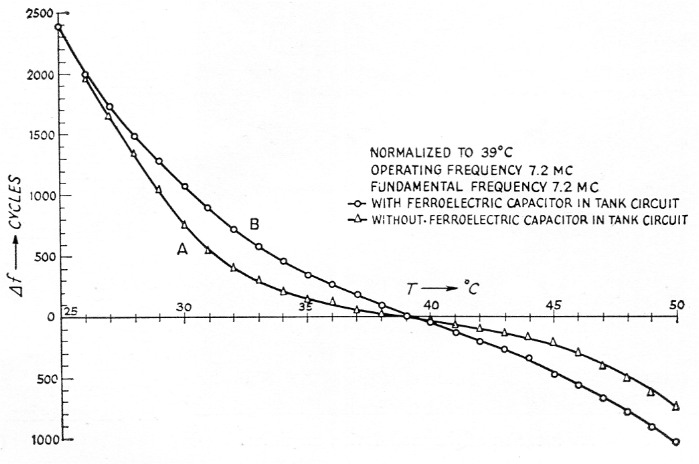
Fig. 7. V.f.o. temperature stability.
(A) Ferroelectric capacitor shorted out.
(B) Including the ferro-electric capacitor.
Summary
The use of ferroelectric capacitors as the modulating elements in a narrow-band f.m. system has proved to be quite useful in the h.f., v.h.f., and u.h.f. regions where conventional reactance tube and phase-modulation methods are unwieldy. The chief advantage of narrow-band f.m. is that it reduces or eliminates certain types of interference to broadcast reception and is quite simple and inexpensive to construct using capacity-modulation techniques. Detection of n.f.m. on a typical a.m. receiver is quite easily accomplished by means of slope detection; i.e., by moving off frequency slightly.
Use of this type v.f.o. in portable and mobile operation where equipment must be restricted in size should prove very helpful.
Acknowledgment
The authors wish to express their appreciation to Mr. Craig Rockafellow, W8QBX, for his assistance in constructing and testing these units.
Notes
- Butler, Diamond, Orr, "Sub-miniature non-linear capacitors for application to VHF wide-range tuning devices," Proc. of the National Electronics Conference, October, 1955, p. 839.
- Butler, "Packaged electric-tuned panoramic receiver for 35-200 Mc range," Proc. of the National Electronics Conference, October, 1957, p. 115.
- This experimental ferroelectric capacitor may be replaced by a commercial unit with only slight changes in the value of the series and shunt capacitors. To the best of our knowledge the Mucon (available from Mucon Corp., 9 St. Francis St., Newark 5, N. J., for approximately $1.50) is the least expensive and most sensitive capacitor commercially available. If there is enough demand, it is quite possible Aerovox might produce units similar to the U. of M. model. Those interested in fabricating their own capacitors should request 0.005-inch thick silvered wafers of HI-Q-91 from Aerovox and consult the reference in Footnote 1 for some information on fabrication.
- C2 could be replaced with another ferroeleetric capacitor if ferroclectric capacitors of 0.3 pF could be made.
T.W. Butler, Jr, W8HGY
G.A. Roberts, W8YNT.