VXO II
Variable-frequency crystal exciter.
Further developments of the VXO circuit described in January 1958 QST. Two applications are discussed: one a two-band Novice version giving discrete crystal-controlled channels, closely spaced; the other, a continuously-variable three-band frequency-control unit with vernier tuning and high stability. Neither approach requires frequency multiplication.
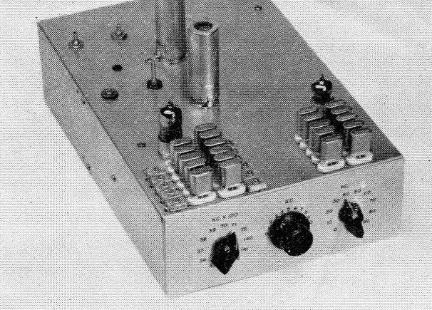
The VXO-II gives continuous crystal-controlled frequency coverage of the 80, 40, and 20 meter bands without frequency multiplication. Fixed crystals are at the left; variable crystals (each covering 10 kc) are at the right. The center knob gives vernier tuning over each 10 kc segment. The mixer and output amplifier tubes are at the rear, with the tuning slugs of the plate coils projecting through the chassis. Tube shields were removed from the oscillator tubes in this view, but should be in place when calibrating.
The crystal oscillator is the ideal means of controlling the frequency of a transmitter. No other technique gives such high stability and resetability with such ease of adjustment. Unfortunately, no other frequency control system is so rigidly inflexible. The user, in the past, has been truly "rockbound" to one spot in the spectrum for each crystal.
The advanced amateur appreciates the advantages of crystal stability for s.s.b. and c.w. operation under conditions of maximum receiver selectivity but, in practice, v.f.o. flexibility takes precedence over other very desirable character, istics. The poor Novice, however, relegated to small overcrowded bands, regulated to mandatory crystal control and "regusted" with his lot, wants a v.f.o. just like the "General" but he has no choice; he must use crystals.
The solution is simple, if money is no object; use multiple-position switches and a crystal for I every channel you wish to work. Space is not a problem because we could switch hundreds of subminiature crystals in the space required by the average v.f.o. However, money is a problem, not only for most of us but for most commercial interests and even Uncle Sam.
Here is a variable crystal oscillator system that solves the crystal and v.f.o. problems at once and throws in a few extra features for good measure. These features are:
- Stability - better than that of the normal crystal oscillator because of the heterodyne principle, which cancels at least part of any small drift caused by temperature changes when using the difference frequency, if both crystals drift in the same direction.
- Resetability - equal to crystal.
- Flexibility - with instantaneous frequency change to any part of band.
- Fast Warmup - exciter is operative and stable within the 45 seconds it takes for tubes to reach operating temperature.
- Multiband Output- without frequency multipliers.
The military, the airlines and many commercial mobile communications users eat their cake and have it too by applying this technique in a family of units called "frequency synthesizers" or "crystal savers." (Try saying "synthesizer" after one beer!) These vary in complexity from equipments that give as many as 2000 crystal-controlled channels from one crystal to those that give 600 channels from 100 crystals. Weight, size and initial cost determine the most practical compromise. In general, it is usually cheaper to use 50 to 100 crystals with simplified circuits than 1 to 10 crystals with complex circuitry.
The synthesizer can solve the amateur's problem just as easily as it solves the commercial interests' problem, and herein lies a tale. If the ham is to build a crystal saver, the circuitry must be relatively cheap, simple and easy to assemble. The rigs to be described are elementary forms of crystal savers. They are cheap, fairly easy to build, super-stable and perfectly resetable. Basically the system is that used in the VXO and other beat-frequency systems described in QST(1),(2) and the Handbook. Two oscillators at different frequencies outside the amateur bands produce new frequencies inside a ham band when combined through a mixer (see Fig. 1).
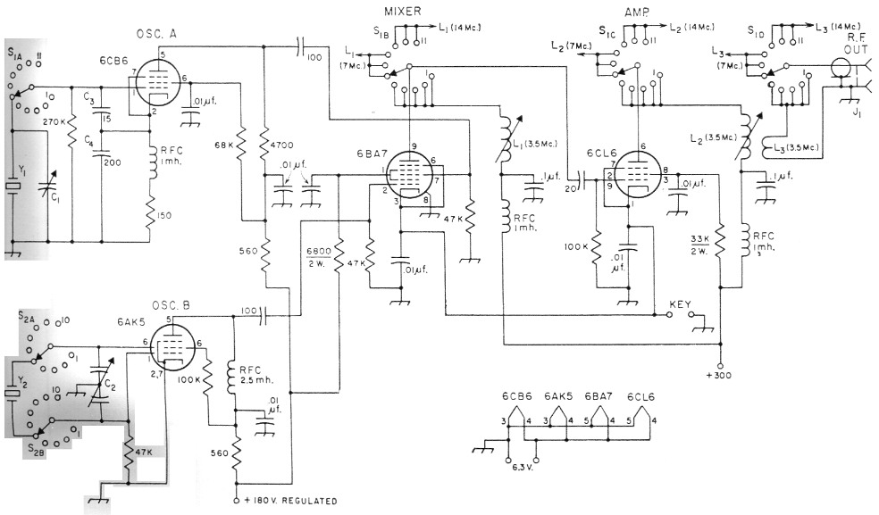
Fig. 1. Circuit of VXO-II, using variable-frequency crystal oscillator for continuous frequency coverage in the 3.5, 7 and 14 Mc bands. Unless indicated otherwise, capacitances are in pF, resistances are in ohm, resistors are ½ watt. 10 nF fixed capacitors are disk ceramic; 100 nF capacitors are paper; others are mica. Bottom ends of L1 coils for the three bands are connected together while top ends connect to contacts on S1B as indicated; similarly for L2 and S1C, and for L3 and S1D.
| C1 | 1.5-20 pF midget mica trimmer (Arco or El-Menco 402). |
| C2 | Dual 140 pF variable modified as described in text. |
| C3,C4 | Silver mica. |
| J1 | Coax fitting, chassis mounting. |
| L1,L2,L3 | See table below. |
| S1 | Ceramic rotary, 4 poles, 11 positions. |
| S2 | Ceramic rotary, 2 poles, 10 positions used. |
| YI,Y2 | See text for frequencies. Y1 crystals used in unit shown are Piezo Crystal Co. VXO-2A; Y2 crystals are VXO-2S. |
To produce a ham channel (from now on we shall refer to mixer output frequencies as channels) we could use a 16,500 kc crystal in oscillator A, and a 20,010 kc crystal in oscillator B, tune the mixer to 3.5 Mc, and out would come the difference between the two frequencies, 3510 kc. One channel from two crystals doesn't seem to be much of a bargain, but watch how fast the rabbits come out of the hat. Add a 16,495 kc crystal to oscillator A, and a 20,020 kc crystal to oscillator B. A little quick arithmetic will show that each crystal in the oscillator A can be used with each crystal in the oscillator B to make four different combinanations in the 3.5 Mc band. We now have four channels for four crystals and are at least even. But wait, it gets even better! The number of channels increases as the square of the number of pairs of crystals we use!
| Pairs of Crystals | Channels |
|---|---|
| 1 | 1 |
| 2 | 4 |
| 3 | 9 |
| 4 | 16 |
| 5 | 25 |
| 6 | 36 |
You can see that for the Novice, at least, we reach a practical limit very rapidly. Ten crystals will give 25 channels in the 3.5 Mc band at 2 kc intervals. We can use the same 20 Mc crystals in oscillator B with five more around 13 Mc in oscillator A to produce 25 difference-frequency channels at 2 kc intervals in the 7 Mc band. Finally, we can add five more crystals to the 20 Mc group and get a total of 50 channels each in the 3.5 and 7 Mc bands at 1 kc intervals. Truly a real lily-gilder with 100 channels and only 20 crystals. See Table 1 for a recommended set of frequencies. It is possible to utilize both sum and difference frequencies to get more channels with fewer crystals, but protection against spurious radiation usually costs more than the few extra crystals. We hope to cover this technique in a later article.
A big problem in adjusting crystals to exact frequencies arises from the fact that the crystals and the using oscillator circuit must be designed as a unit. Even when this is done, the usual practice is to allow 20 cycles per megacycle as a manufacturing tolerance and then adjust the crystals to exact frequency in the circuit. This is the function of the trimmer capacitors in parallel with the crystals. Crystals with low activity, when so trimmed, lose output voltage or stop oscillating. Therefore active crystals are required. It is to be expected that crystals made for other oscillators will operate at frequencies sometimes several kc from those marked on the cases, with the differences becoming greater as the frequency rises.
Since attempting to trim some surplus crystals to frequencies in the schedules may make them inoperative, the trimmers can be eliminated. The frequency spacings in the schedules are not really important. It's just a convenience to be able to think in exact frequencies and uniform steps rather than odd values. Either approach gives satisfactory coverage of a band. If exact frequencies are desired, there are several good articles in past QSTs(3) that tell how to make crystal frequency adjustments. Be sure to adjust the crystals to frequency in the VXO oscillator you build.
Construction hints
The basic VXO-II exciter provides a series of fixed frequencies as described above and is the type recommended for Novice use. But since the Novice license period is only a temporary phase of the ham's career, it makes good sense to look ahead a bit in building equipment, and the VXO-II unit shown in the photographs has been designed with eventual "General" operation in mind. It provides for continuously-variable crystal control as described later, but needs no modifications to be used with the crystal combinations given in Table 1.
| Novice operation with 1 kc channel spacing on 80 and 40 meter. 20 crystals, 100 channels. Mixer output must be tuned to desired difference channel. | ||||||||
| Δ Freq. | Crystal Freq. A | Crystal Freq. B | Δ Freq. | Crystal Freq. A | Crystal Freq. B | Δ Freq. | Crystal Freq. A | Crystal Freq. B |
|---|---|---|---|---|---|---|---|---|
| 3700.5 | 16300 | 20,000.5 | 3735.5 | 16270 | 20,005.5 | 7170.5 | 12830 | 20,000.5 |
| 3701.5 | 20,001.5 | 3736.5 | 20,006.5 | 7171.5 | 20,001.5 | |||
| 3702.5 | 20,002.5 | 3737.5 | 20,007.5 | 7172.5 | 20,002.5 | |||
| 3703.5 | 20,003.5 | 3738.5 | 20,008.5 | 7173.5 | 20,003.5 | |||
| 3704.5 | 20,004.5 | 3739.5 | 20,009.5 | 7174.5 | 20,004.5 | |||
| 3705.5 | 20,005.5 | 3740.5 | 16260 | 20,000.5 | 7175.5 | 20,005.5 | ||
| 3706.5 | 20,006.5 | 3741.5 | 20,001.5 | 7176.5 | 20,006.5 | |||
| 3707.5 | 20,007.5 | 3742.5 | 20,002.5 | 7077.5 | 20,007.5 | |||
| 3708.5 | 20,008.5 | 3743.5 | 20,003.5 | 7178.5 | 20,008.5 | |||
| 3709.5 | 20,009.5 | 3744.5 | 20,004.5 | 7179.5 | 20,009.5 | |||
| 3710.5 | 16290 | 20,000.5 | 3745.5 | 20,005.5 | 7180.5 | 12820 | 20,000.5 | |
| 3711.5 | 20,001.5 | 3746.5 | 20,006.5 | 7181.5 | 20,001.5 | |||
| 3712.5 | 20,002.5 | 3747.5 | 20,007.5 | 7182.5 | 20,002.5 | |||
| 3713.5 | 20,003.5 | 3748.5 | 20,008.5 | 7183.5 | 20,003.5 | |||
| 3714.5 | 20,004.5 | 3749.3 | 20,009.5 | 7184.5 | 20,004.5 | |||
| 3715.5 | 20,005.5 | 7150.5 | 12850 | 20,000.5 | 7185.5 | 20,005.5 | ||
| 3716.5 | 20,006.5 | 7051.5 | 20,001.5 | 7186.5 | 20,006.5 | |||
| 3717.5 | 20,007.5 | 7152.5 | 20,002.5 | 7187.5 | 20,007.5 | |||
| 3718.5 | 20,008.5 | 7153.5 | 20,003.5 | 7188.5 | 20,008.5 | |||
| 3719.5 | 20,009.5 | 7154.5 | 20,004.5 | 7189.5 | 20,009.5 | |||
| 3720.5 | 16280 | 20,000.5 | 7155.5 | 20,005.5 | 7190.5 | 12810 | 20,000.5 | |
| 3721.5 | 20,001.5 | 7156.5 | 20,006.5 | 7191.5 | 20,001.5 | |||
| 3722.5 | 20,002.5 | 7157.5 | 20,007.5 | 7192.5 | 20,002.5 | |||
| 3723.5 | 20,003.5 | 7158.5 | 20,008.5 | 7193.5 | 20,003.5 | |||
| 3724.5 | 20,004.5 | 7159.5 | 20,009.5 | 7194.5 | 20,004.5 | |||
| 3725.5 | 20,005.5 | 7160.5 | 12840 | 20,000.5 | 7195.2 | 20,005.5 | ||
| 3726.5 | 20,006.5 | 7161.5 | 20,001.5 | 7196.5 | 20,006.5 | |||
| 3727.5 | 20,007.5 | 7162.5 | 20,002.5 | 7197.5 | 20,007.5 | |||
| 3728.5 | 20,008.5 | 7163.5 | 20,003.5 | 7198.5 | 20,008.5 | |||
| 3729.5 | 20,009.5 | 7164.5 | 20,004.5 | 7199.5 | 20,009.5 | |||
| 3730.5 | 16270 | 20,000.5 | 7165.5 | 20,005.5 | ||||
| 3731.5 | 20,001.5 | 7166.5 | 20,006.5 | |||||
| 3732.5 | 20,002.5 | 7167.5 | 20,007.5 | |||||
| 3733.5 | 20,003.5 | 7168.5 | 20,008.5 | |||||
| 3734.5 | 20,004.5 | 7169.5 | 20,009.5 | |||||
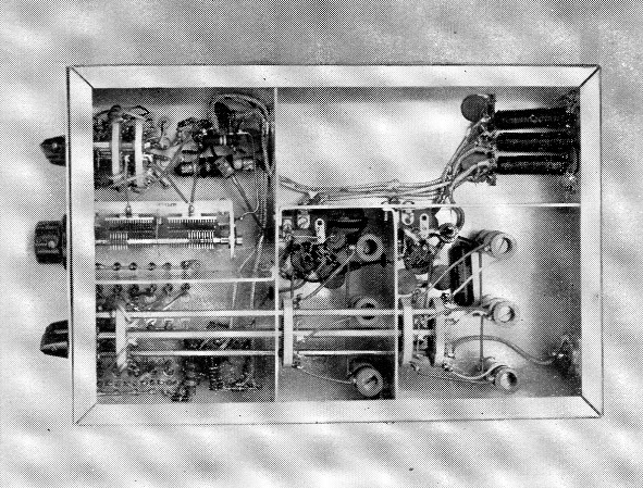
The bottom of the VXO-II is divided into compartments enclosing the various stages. The variable oscillator is at the upper left, fixed oscillator at the lower left, mixer at bottom center, and amplifier at lower right. The band switch, bottom, is an assembly of standard switch components, with one switch position for each 100 kc band. The upper-right compartment houses incoming supply leads and filters TVI (not shown in Fig. 1) of the type described in the TVI chapter in the Handbook.
| Band | L1 | L2 | L3 |
|---|---|---|---|
| 3.5 Mc | 88 turns No. 36 | 100 turns No. 36 | 5½ turns |
| 7 Mc | 30 turns No. 31 | 36 turns No. 31 | 4 turns |
| 14 Mc | 26 turns No. 24 | 31 turns No. 24 | 3 turns |
All coils on National XR-51 (brass-slug) forms, ½ inch diam., 11/16 inch winding space. L1 and L2 close-wound with enameled wire; L3 is plastic-covered hook-up wire wound at cold end of L2.
The VXO-II as shown is built on a 8 × 12 × 3-inch chassis. The 6CL6 amplifier was deemed necessary for two reasons - to give additional selectivity for preventing radiation of unwanted mixer products outside the bands, and to provide additional output power. When used with transmitters having sufficient tuned stages and gain, the amplifier portion may not be needed.
Only a few precautions are necessary in assembling such a unit:
- Assemble all parts except the switches.
- Make crystal leads as short as possible.
- Attach leads to the crystal sockets, then mount the switches and connect these leads.
- Set C2 to about 15 per cent of full capacitance at a point that brings the 20 Mc bank of crystals to their correct frequencies. Remove the knob and save it for the day the General class license arrives. For Novice operation only the crystal switches will be used to change frequency.
- Shield, bypass and filter all power leads.
The only nonstandard component is C2. This is a Hammarlund HFD-140 dual 140 pF capacitor which has had plates removed until there are 7 rotor and 8 stator plates (approximately 60 pF) in the control-grid section and 10 rotor and 11 stator plates (80 pF) in the screen-grid section.
If you make an exact duplicate with the Piezo crystals specified, the trimmers C1 will adjust the frequencies of the crystals to the exact frequencies in the schedule. If surplus crystals are used, most of which are available in the FT-243 and CR-1/A holders, a larger chassis will be needed and the quartz itself will have to be adjusted to the frequencies indicated when following the suggested schedule. Adequate output for a Novice band will be available with the mixer coils tuned to the center frequencies of the respective bands of operation. For a "General" band, stagger tuning will be necessary. Experimenting with turns may be required for full output. There are at least 1% watts available with 300 volts on the plate of the amplifier. This is adequate power to drive most crystal oscillators or buffers.
Continuous Coverage
Now see how the VXO-II solves the advanced amateur's problem by covering every frequency in the band instead of taking them in discrete steps. In addition, see how to convert from Novice to General operation merely by adding the knob you have been saving and changing crystals. All things seem possible through heterodyning.
Heterodyning permits:
- using high-frequency crystals capable of large frequency swings and no-sacrifice of stability from the ham viewpoint;
- direct output in the desired band without multipliers;
- decade switching and tuning. (Note: S1 selects the nearest 100 kc, s2 selects the nearest 10 kc, and C2 tunes to any frequency in between the 10 kc steps);
- excellent reset-ability;
- extreme vernier tuning with almost instantaneous band coverage;
- 45 second warm up;
- high stability (15 cycles on 7 Mc. during the first hour after the 45 second warm up.)
Hams have known for years how to shunt a variable capacitor across a crystal to shift its frequency a small amount without having it fail or become erratic.
The permissible shift increases with frequency. Fundamental crystals permit acceptable swings. Overtone crystals have such high Qs that they are comparatively little affected. A coil in series with the crystal, as used in the VXO-I,(1) can increase the tuning range almost indefinitely but the greater the swing the poorer the stability, until finally the result is no better than with any other variable-frequency oscillator.
Oscillator B (right-hand knob in the photograph) covers the range from 20,000 to 20,100 kc by switching 10 crystals in steps of 10 kc Capacitor C2 (center knob) "tunes" the crystal in the circuit over the 10 kc increment, with 500 to 800 cycles overlap at each end. The ten crystals thus provide all the frequencies in the 100 kc range. Oscillator A (left knob) provides fixed crystal-controlled frequencies at 100 kc intervals which, when mixed with the 20,000-20,100 kc in oscillator B, produce different frequencies as follows:
| Oscillator B 20.0 to 20.1 Mc minus frequencies below in Oscillator A Mc | Equals frequency range |
|---|---|
| 16.5 | 3500-3600 |
| 16.4 | 3600-3700 |
| 16.3 | 3700-3800 |
| 16.2 | 3800-3900 |
| 16.1 | 3900-4000 |
| 13.0 | 7000-7100 |
| 12.9 | 7100-7200 |
| 12.8 | 7200-7300 |
| 6.0 | 14,000-14,100 |
| 5.9 | 14,100-14,200 |
| 5.8 | 14,200-14,300 |
At this point oscillator A ran out of switch positions, but 12 position switches are obtainable. Three ham bands were included here merely to show how versatile the technique can be. It also points up how nice it is to have a knob that always tunes the same number of kilocycles irrespective of the band used, and without having to multiply by 2, 4, 6, or 8. Nevertheless, most hams already have transmitters with multipliers and thus will be interested only in the 3.5 to 4 Mc range. The other switch and socket positions can be used for special out-of-band net frequencies like MARS. The capacitors C1 are used to trim the oscillator A crystals to exact multiples of 100 kc. No trimmers are used in oscillator B because every bit of circuit capacitance available is needed to provide the tuning range. Also, no two crystals provide exactly the same frequency change for a given capacitance change, so the trimmers would only aggravate this condition. This lack of uniformity in tuning the 10 kc steps is the only weakness in this arrangement. It could be solved by methods too expensive to incorporate here.
Any type of good crystal can be used in oscillator A, but only crystals designed for oscillator B will give the required over 10 kc swing. Overtone crystals will not shift enough because of their extremely high Qs. Crystals with less than 10 kc swing can be used if enough of them are included to cover 100 kc. As an alternative, 10 crystals in oscillator A at 50 kc intervals mixed with the 10 crystals in oscillator B that swing 5 kc would work just as well for 3.5 Mc.
"Keep crystal leads as short as possible in oscillator B" is the only special warning on the wiring. The tube shields are an integral part of the alignment - be sure they are in place when making adjustments.
The VXO-II has a minimum output of 1 watt into 52 ohm on all frequencies, with 1½ watt on 80 and 40.
Now some words of warning!
All frequencies used in the schedules have been chosen so that their fundamentals and harmonics fall outside the ham bands. This is nice for brother hams but the FCC doesn't like harmonics to fall on other services either. The 6CL6 amplifier was added to the original model in order to reduce the strength of out-of-band harmonics to a minimum, but an on-the-air test is the best insurance. The rig works fine here but play it safe. Key clicks, if apparent, must be treated as with any other rig. Plate voltage to the oscillators should be regulated, although the rig is pretty insensitive to voltage changes.
Notes
- Shall, "VXO - a variable crystal oscillator," QST, January, 1958.
- Bartlett, "A beat-frequency exciter for better C.W. signals," QST, June, 1952.
- For example, Newland, "A safe method for etching crystals," QST, January, 1958.
Herman Shall, W3BWI.