6146s in parallel
180 Watt C.W - 130 Watt phone.
For some time, our correspondence has indicated more interest in transmitters running a power input of about 150 watts than those of any other input rating. This clean-cut straightforward job should be a popular item.
The amplifier shown in the photographs uses a pair of 6146 tubes in parallel and is designed to cover all amateur bands from 3.5 to 30 Mc. It can be operated at a maximum input of 180 watts on C.W or 130 watts on phone. It may also be operated linear, Class AB1, for s.s.b. operation.
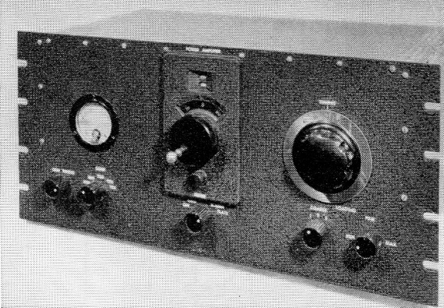
Front panel layout. Controls along the bottom from left to right: grid-tuning capacitor, grid band switch, meter switch, switch for fixed output capacitors (coarse loading), variable output capacitor (fine loading). The large dial in the center drives the rotary inductor, while the large knob (Millen 10008) turns the plate tank capacitor.
Circuit details
The input circuit is a parallel-tuned tank link-coupled to the driver. Two separate coils are used in the grid circuit. They are used in series on 80 and 40 meters, while on 20 meters and higher one coil is entirely shorted out, as well as the required number of turns on the other coil, to obtain correct tuning of the circuit. The low-frequency link is also shorted out on all bands above 7 Mc. in order to avoid difficulty in obtaining sufficient grid drive. The entire circuit is tuned by a 100 pF variable capacitor, C1.
The unit is neutralized by the capacitive-bridge method, while the combinatiogs of L5R1 and L6R2 are adjusted to suppress any V.h.f. parasitic oscillation.
The rotary inductor (L8) used in the pi-network output circuit came from a surplus antenna-tuning unit and has a value of approximately 10 microhenrys; however, a Johnson type 229-201 inductor will work just as well and requires less space. The rotary inductor is used on all bands except 10 meters where a separate coil (L7) is used.
The required value of output capacitance is obtained from a three-gang, 365 pF-per-section broadcast-type variable, C4, with all sections connected in parallel. This capacitor is supplemented by two 400 pF fixed capacitors, C5 and C6, to give a total of approximately 1900 pF.
The meter used in this unit reads 1.5 mA full scale. It is shunted to give full-scale readings of 15 mA in the GRID position of the meter switch, 30 mA in the SCREEN position, and 300 mA in the PLATE position. Any meter with a full-scale reading of about 1 mA may be used. Shunts are wound with copper wire following the procedure outlined in the Handbook.
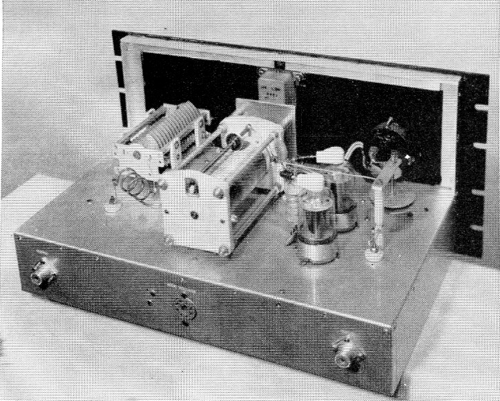
Rear view of amplifier. The shafts of the tuning capacitor and rotary inductor are spaced 3½ and 8½ inches from the left side of chassis. The 10 meter coil can be seen behind the tuning capacitor. The 6146 sockets are spaced 3½ and 6 inches in from the back of the chassis and 4¼ inches in from the right side. The neutralizing capacitor and r.f. choke are mounted in a line centered between the 6146 sockets.
All power wiring is done with shielded wire, with adequate bypassing and filtering to prevent harmonic radiation.
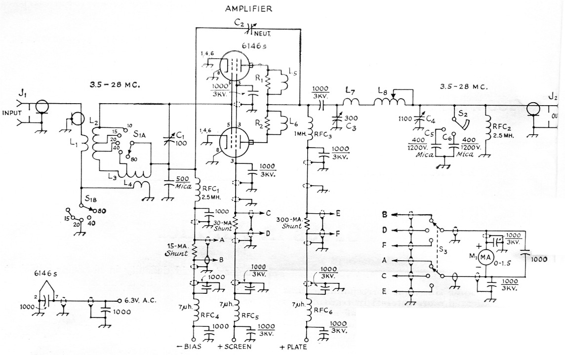
Fig. 1. Circuit of the parallel 6146 amplifier. Capacitances are in pF. Unless otherwise specified, capacitors are disk ceramic.
| C1 | 100 pF midget variable (Hammarlund HF-100). |
| C2 | Neutralizing capacitor (see text and Fig. 2). |
| C3 | 300 pF variable (Johnson 154-2, National TMS-300 or similar). |
| C4 | 365 pF triple-gang broadcast-replacement type variable, sections in parallel. |
| C5,C6 | 400 pF 1200 or 2500 volt mica. |
| J1,J2 | Chassis-mounting coax receptacle (S0-239). |
| L1 | 3 turns hookup wire at cold end of L2. |
| L2 | 30 turns No. 20, 5/8 inch diam., 16 t.p.i., tapped at 4½, 9½ and 20½ turns from grid end (B & W 3007 or Airdux 5161). |
| L3 | 26 turns No. 24, 1 inch diam., 32 t.p.i., tapped 8 turns from junction of L2 and L3 (B & W 3016 or Airdux 832T). |
| L4 | 12 turns some as L3 (see text). |
| L5 | L6 5 turns No. 18 on 100 ohm 1 watt resistor. |
| L7 | 3 turns No. 10, ¾ inch diam., 1¾ inches long. |
| L8 | 10 µH rotary inductor (see text). |
| M1 | 0-1.5 d.c. milliammeter. |
| R1,R2 | 100 ohm, 1 watt, noninductive. |
| RFC1,RFC2 | 2.5 mH r.f. choke (National R-50). |
| RFC3 | 1 mH 600 mA r.f. choke (National R-154U). |
| RFC4,RFC5,RFC6 | 7 µH v.h.f. choke (Ohmite Z-50). |
| S1 | 2 pole 5 position ceramic rotary switch (Centralab PA-2003). |
| S2 | Progressively-shorting rotary switch (Centralab PA-2042). |
| S3 | 2 pole 3 position phenolic rotary switch (Centralab PA-1103). |
Construction
The amplifier is built on a 10 × 17 × 3 inch aluminum chassis which is mounted on a standard 8¾ × 19 inch rack panel. The chassis is placed so that the bottom of the chassis is 3/8 of an inch up from the bottom edge of the panel. The layout of components can be seen from the photographs. The grid coils are mounted on insulated terminal strips and are set at right angles to each other. Both coils are made from Miniductor coil stock. Coils L3 and L4 are made from one piece of stock. Counting in about 30 turns from one end, the wire is cut at this point. One half turn is then unwound from each coil at the point where the cut was made, leaving two coils on the same support bars, separated by one turn. The wire is then removed from the ends of the coils until the correct number of turns is obtained in each. The grid tuning capacitor must be insulated from ground. Since this capacitor has a built-in L bracket, the foot of the bracket is mounted on a ½ inch standoff insulator, and the rotor is turned through an insulated shaft coupling. The neutralizing capacitor used was a home-brew unit having a maximum capacitance of about 10 pF. It is sketched in Fig. 2. However, any commercial unit having about the same capacitance, such as the Hammarlund NZ-10, will work just as well.
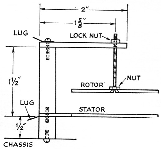
Fig. 2. Sketch showing constructional details of the neutralizing capacitor. The plates are identical 2 inch disks of As-inch aluminum, except that the stationary plate has a mounting ear at one side and the rotary plate is drilled and countersunk at the center for a 2 inch flathead 6-32 screW The head is peened to keep it flush with the disk. The insulating support is two ceramic standoff insulators, joined by a piece of threaded rod with the ear of the stationary plate sandwiched in between. The rotor support is a strip of ½ inch aluminum, threaded for the rotor screW
The meter switch shown in the photographs has ceramic insulation, but a switch with phenolic insulation will serve the purpose adequately, and such a unit is specified in the parts list.
The rotary inductor is mounted centrally on the chassis and is driven through a counter dial. The dial pictured is a Millen unit that was obtained on the local surplus market. A counter dial such as the Groth type would, no doubt, require less space and be easier to mount. The plate tuning capacitor is mounted on the panel at the same height as the inductor shaft to preserve symmetry. All paint on the panel, where any mechanical joint is to be made, should be removed to insure good electrical contact.
The output capacitor and the switch for the fixed capacitors are mounted beneath the chassis with the same panel height and spacing as the grid-tank components.
To complete the shielding, the chassis is fitted with a bottom plate and a cover made from Reynolds perforated stock.
Adjustment and operation
Before applying excitation the amplifier should be checked for parasitic oscillation by following the procedure outlined in the Handbook.
The amplifier should then be neutralized. To do this, tune the grid and plate circuits to resonance in the 10 meter band. Plate and screen voltages should be disconnected and grid drive applied to give rated grid current. The meter is set to read grid current and the neutralizing capacitor adjusted until a setting is found where there is no kick in grid current when the plate capacitor is tuned through resonance.
The various operating voltages for all classes of operation are given in the following table:
| Plate Voltage | Screen Voltage | Grid Bias | Grid Current | Screen Current | Plate Current | Power Input |
|---|---|---|---|---|---|---|
| (Class C C.W.) | ||||||
| 500 | 170 | -66 V | 5 mA | 18 mA | 270 mA | 130 W |
| 750 | 160 | -62 V | 6 mA | 22 mA | 240 mA | 180 W |
| (A.M. Phone) | ||||||
| 600 | 150 | -87 V | 6 mA | 15 mA | 220 mA | 130 W |
| (AB Linear) | ||||||
| 600 | 200 | -50 V | 0 | |||
| 750 | 200 | -50 V | 0 | |||
| The filament requirements are 6.3 volts at 2.5 amperes. | ||||||
The grid bias for Class C operation may be supplied from an external fixed supply, a grid-leak resistor, or a combination of both. The bias for Class AB1 should come from a fixed supply. It should be remembered that when this unit is used on c.W it is not keyed and therefore some method of limiting the plate power input to under 50 watts during key-up conditions should be provided. This can be done by using separate fixed supplies for grid bias and screen voltage or, if the screen voltage is taken from the plate supply through a resistor, and grid bias supplied from a grid-leak resistor, a clamp-tiibe circuit may be used. For phone operation the screen voltage should be obtained from the plate supply through a dropping resistor.
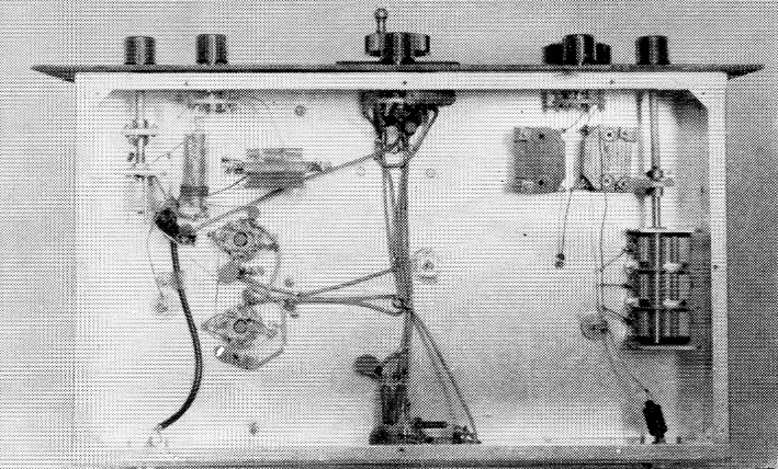
Under-chassis view of amplifier. Grid-tank components are in upper left, output capacitors in upper right. The grid tank-capacitor shaft and the output-capacitor shaft are approximately 1½ inches in from edge of chassis, while the shafts in the grid-tank and output circuits are spaced about 2 inches. The meter switch is in the center. Connections from output coils and neutralizing capacitor are brought through the chassis with feed-through insulators. Clustered around the power socket in lower center are the v.h.f. chokes and bypass capacitors.
A grid-dip meter is useful for initial tune-up. For 80 meters the plate tank capacitor should be set to almost maximum capacitance and the rotary inductor adjusted for resonance. The setting of the inductor should then be logged for reference. On 40 meters the capacitor is set to one half its maximum value and the same procedure followed. On 20 meters the capacitor is set so that the plates are only slightly meshed, and on 15 and 10 meters it is set as close to minimum capacitance as possible. After the settings of the inductor are known for each band, the inductor is set to the predetermined value and the circuit resonated with the plate tank capacitor.
With an exciter connected to J1, the grid circuit should be tuned for maximum drive. The output of the exciter should then be adjusted to give rated grid current. An exciter capable of at least four watts output should be used. With plate and screen voltage applied, the plate circuit should be tuned to resonance and the amplifier loaded to the desired input by means of the "fine" and "coarse" loading controls while maintaining resonance with the plate tank capacitor.
Fred F. Reed, K2RHG.