How to wind your own transformer
Small transistor power supplies at low cost.
With an old audio-transformer core and a small amount of wire, it is no trick at all to cut the cost of a small transistor power supply considerably by winding your own transformer. W6ACT shows how a satisfactory design may be determined experimentally.
Transistors are getting cheaper. By taking advantage of this fact and by building the transformer it is easy to build a satisfactory power supply for a receiver or a mobile transmitter. Most of the transistor power transformers on the market are quite expensive, but an old audio transformer can be rewound to make a suitable substitute. If the core is a half inch or so in thickness it will do. Not much iron is necessary as the frequency will be considerably higher than 60 cycles.
Determining Ampere-turns
The first step is to strip off the old winding and make a wood winding form with the same cross-sectional dimensions as the core. A temporary trial winding is then made to use in determining the proper number of turns for the final winding. To make this winding, cut a strip of cardboard the same width as the opening in the window of your transformer core. Wrap a single layer of this cardboard around the wood form and secure it with a turn of friction tape. On opposite sides of the form, lay strips of tape, sticky side out, lengthwise on the form. When the winding is complete, the ends of these two pieces of tape are folded back over the winding to hold it in place.
Now wind 20 or 30 turns of enameled wire around the center of the form on top of the cardboard, and tape. Any wire size from 16 to 20 will do. When the first coil is in place, put on two more similar coils, one on either side of the first. There is nothing critical about these coils, and smaller wire may be used. When the three coils are wound, tape them up and assemble them on the core.
The next step is to connect the first coil to a 6-volt storage battery in series with a rheostat, a switch and a d.c. ammeter. To one of the other coils a low-voltage source of 60-cycle a.c. should be connected. A voltage of 2 to 6 is about right. The third coil should be connected to the vertical plates of an oscilloscope. The sweep frequency may be almost any value since any pattern will give the desired indication.
Turn on the a.c. and there should be a picture on the scope face. Now close the d.c. circuit and increase the current by adjusting the rheostat. As this is done, the pattern on the scope will decrease in height. Advance the rheostat control until the pattern just disappears, and read the current. When this current is multiplied by the number of turns in the first coil, the product is the number of ampere-turns necessary to saturate the core. The operation of the multivibrator-type circuit requires that the core saturate, and this should occur without exceeding the maximum collector-current rating.
Primary winding
Having determined the number of ampere-turns to saturate the core, you may proceed to design the final winding. To do this, first choose the power transistors you will use, and find the collector-current rating from the manufacturer's literature. CBS Hytron 2N255 and 2N256 are low in price and will work well. Divide the ampere-turns for saturation by the collector current and you have the number of turns for the primary winding of your transformer. The proper wire size may be found in the wire table in all editions of the ARRL Handbook. There will be two coils and each will conduct only half the time, so the wire need be only large enough to carry half the rated current of the transistor.
Before winding the coil, make a couple of removable ends with square holes to slip over the wood form to confine the winding to the space available in the core window. An insulating base of thin cardboard or heavy paper should be put on the wood form, with strips of tape as before. For the final primary coil, two strands of enameled wire are wound in parallel. Cut two pieces of the primary wire and holding them parallel, wind on the number of turns determined above. Be sure to leave sufficient lead length at the starting end for connections. When this double primary coil has been wound, fold the tape ends down to hold it in place and wrap it with a thin layer of insulating paper.
Bias winding
On top of this layer of paper lay two more strips of tape to hold the next winding. This is the base-bias winding and is put on in the same manner as the primary, winding two wires in parallel. For this winding smaller wire may be used. No. 28 is about right. Wind on about one fifth as many turns as in the primary winding.
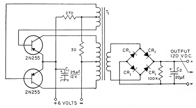
Fig. 1. Suitable circuit for a small transistor power supply. Resistances are in ohms and resistors are 1 watt. C1 and C2 are electrolytics. See text referring to connection of CI. The rectifiers, CRI, are Sarkes Tarzian type M-150. The transformer T1 is described in the text.
The secondary coil goes on next, but before starting it you had best test out what you already have so as not to waste the time and material on the secondary coil if the primary is not going to work.
There are many circuits which will oscillate with the power transistors available. The circuit shown in Fig. 1 has worked well in a receiver power supply. Cl is a hash suppressor. It should be connected from the ungrounded side of the 6-volt line to chassis. If the positive side of the line is grounded, the capacitor should be connected from negative to chassis with the positive side of the capacitor to chassis.
Testing the primary
Assemble the partial winding on the core and wire up your favorite circuit. Be very careful to connect the d.c. supply with the correct polarity, or the transistors will be ruined. In case you are not familiar with transistors, there is a little trick to help in remembering the various polarities. Transistors are designated p-n-p or n-p-n and these letters refer to the polarities of the elements. The center letter gives the polarity of the collector and "center" and "collector" both begin with c. How can you miss?
When power is applied, the circuit should oscillate and you will know it as you can hear it buzz. If all goes well and it oscillates, you are ready to design the secondary winding. Wind five or six turns over your coil by threading them through the core. Apply power and measure the voltage on this temporary secondary coil. It is an a.c. voltage, so use an a.c. voltmeter. By dividing the number of volts by the number of turns, you find the volts per turn, and by dividing the volts per turn into the desired secondary voltage, the number of turns for the secondary winding is found.
Now take the transformer apart, put the winding back on the form and wind on the secondary coil. Use a wire size that will just about fill the remaining space in the core opening. If a center tap is desired, wind two secondary coils. For the same rectified output voltage, each secondary must have the number of turns previously estimated. However, the wire need be rated for only half the load current. The two coils should be connected so that they assist. If little or no voltage output is obtained when the two windings are connected in series, reverse connections to one of the coils. In general, the secondary current that can be drawn safely without damaging the transistors will be approximately twice the collector current rating divided by the ratio of secondary turns (one secondary if center tap is used) to one half the primary turns.
A power supply built by the method described above worked quite well. 2N255 transistors were used and the supply was designed to work from a 6-volt battery. The collector current runs about 2 amperes and the open-circuit secondary voltage is about 120 volts d.c.(1) This particular supply was designed to operate a BC-474 surplus receiver which requires 90 volts and, under load, the supply delivers just about that voltage. The rectifiers used were Sarkes Tarzian M-150 silicon units and they cost 90 cents each. The transistors are listed at $1.32 each. By using a junk-box transformer, all the rest of the components can be purchased new for less than $10.00.
Such details as the exact number of turns and wire sizes which were used in the supply described here were purposely omitted since this article was intended to enable you to design your own power supply.
Notes
- Unless special transformer core material is used, transient spikes of collector voltage may develop sufficient amplitude to damage the transistor in time. If a check on an oscilloscope shows spikes exceeding the maximum collector voltage rating, it would be advisable to connect a 25-µf. 50-volt electrolytic capacitor and a 200-ohm resistor in parallel from each base to chassis, connecting the positive side of the capacitor to the base. - Ed.
C.A. THUNEN, W6ACT.