A cool kilowatt plate transformer
Transformer winding became practically a lost art when power transformers started to be plentiful and inexpensive. Today, though, you might save money on a high-power job by making it yourself. Perhaps even more appealing is the prospect of reducing size and weight by using the newer types of core that don't seem to have invaded the amateur plate-supply field commercially.
The plate transformer to be described, although small - only 6_3/8 by 6_3/8 by 7¼ inches - delivers a kilowatt input at 3000 volts d.c. to the writer's 450TH. Furthermore, it is not difficult to construct and assemble, thanks to the use of a two-piece "C"-type core. The secret is in the use of a grain-oriented silicon-steel core, made in a variety of sizes and sold under various trade names. The core used in the transformer shown is a "Silectron" type AA-520, having a cross-sectional area of 5 square inches and using 12-mil material.(1) The secondary can handle an output current of 500 ma. without any trouble, since the twire size has been selected on the conservative basis of about 1000 circular mils per ampere.
The basic equation for transformer design is
![]()
where:
Nu = Number of primary turns
Ep = Primary voltage
A = Core area in square inches
F = Stacking factor (0.95 for 12-mil material)
f = Frequency in cycles per second
B = Flux density in gausses (15,000 for Silectron)
Substituting the values given,
![]()
For a supply voltage of 230 the number of turns should be doubled - i.e., 188 turns for this core. No. 10 wire is used for the 115 volt primary in the transformer shown, but if a 230 volt primary is used the wire size may be reduced to No. 13. Formvar insulation on both primary and secondary is recommended.
In the actual construction, half the primary is wound on each leg, as is half the secondary. The cross section of the final assembly is shown in Fig. 1. The coils are assembled on two bobbins made as shown in Fig. 2, one for each leg of the core. One-half of the primary, 47 turns, is wound directly on each bobbin after taping as indicated in Fig. 1. The primary is then similarly covered with tape. The double layer of varnished cambric is made by lapping each turn over half the preceding one.
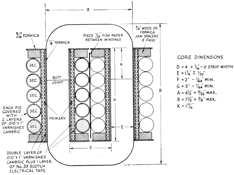
Fig. 1. Cross section of the transformer assembly. Dimensions given are for the Arnold Engineering Company type AA-520 grain-oriented silicon steel core. If a core with other dimensions is used, the bobbin shown in Fig. 2 should be modified accordingly. Spacer thickness should be such as to hold the windings tightly in place to prevent vibration.
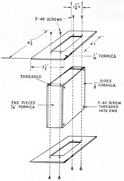
Fig. 2. Bobbin construction. The parts are held together by small machine screws threaded into the Formica. The bobbin should be a snug fit for the core, but care must be used to keep its over-all length slightly less than that of the core opening so the two halves of the core can be butted tightly together.
A 94 turn primary for 115 volt figures out to be about 1.22 volts per turn; thus the number of secondary turns required for 6000 volts r.m.s. would be 6000/1.22, or 4920 turns - in round figures, 5000 turns. A little figuring showed that No. 25 (320 circular mils) would fit in the space. But the thought of winding all those turns was rather staggering. The problem was solved by adopting the method of winding the secondary in ten pies of 500 turns each, and a special tool shown in the photograph was made up for the purpose. The coils are scramble-wound, and go on easily if the handle of the tool is held in the left hand while the right pulls the wire off its spool and winds it on the tool in circular fashion. After winding a few pies it was found that a complete 500 turn coil could be wound in 12 minutes. Each pie is wrapped with 1 inch varnished cambric tape, overlapped ½ inch to give double insulation.
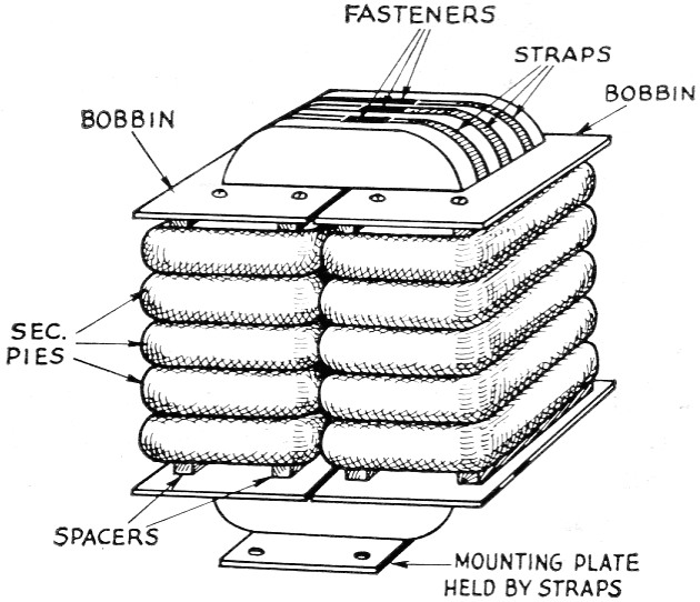
Fig. 3. Assembly before final wrapping. The core pieces are held tightly together by steel straps of the type used for fastening crates. If these and the machine for tightening them are not available, chimney-mour.ting straps for TV antennas are a possible substitute. Terminals for primary and high-voltage leads can be machine screws mounted in the bobbin ends.
In assembling the bobbins and core, make sure that the core faces are free from dirt, hair, or small particles of any kind. The writer applied a very thin film of silicone grease to the core faces after cleaning, in order to keep them from rusting. The coils should of course be connected series aiding (so the voltages add), and the center tap as well as the two ends of the secondary winding should be brought out to terminals.
Although no exact cost run-clown has been made on the transformer, the cost should he in the vicinity of $30 to $35. The core is the major item, its price being slightly over $15. Another $10 should take care of the wire. This particular transformer, weighing about 35 pounds, has taken over the plate-supply job formerly handled by a much bulkier 2 kVA surplus transformer that was too heavy for one man to handle - and runs stone cold while doing it.
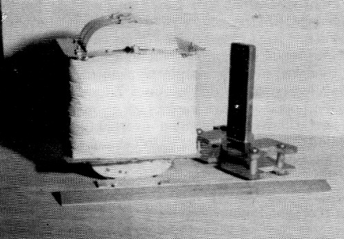
The completed transformer, and tool for winding secondary pies. The wire is wound on the four metal pillars at the corners of the tool. One side of the tool is removable so the pie can be slipped off after completion. Sides of the tool are cut away as shown so that the pie can be partially taped to keep it together when removing. Too! dimensions should be chosen to make the pie fit reasonably snugly over the bobbin.
Notes
Robert B. Coats, W9ESD.