A crystal-controlled converter for 1296 Mc
Modern receiving techniques for our lowest microwave band.
Recent issues of QST have carried reports of new DX records for the 1215-Mc. band. The author of this article was one of the moving spirits in this work, and the converter he describes here has been employed extensively, not only in these recordmaking expeditions, but regularly in his home station in Los Angeles. It brings to the edge of the microwave region the high-stability narrow-band techniques that have proven effective on all lower amateur frequencies.
Few articles on equipment for the 1215-Mc. band have appeared in amateur publications. Of these, only two described crystal-controlled transmitting or receiving gear.(1) In any new field of amateur communication it is well not to let a particular circuit or mechanical arrangement become too standardized in the mind of the experimenter. New schemes for transmitters, receivers or antennas for 1215 Mc. may or may not be superior to the few that have already appeared in print, but each should be given due consideration, before relegating the band to cut-and-dried circuitry, as has happened on our lower frequencies.
In designing the crystal-controlled converter described here we tried to use circuits that could be duplicated without special equipment not generally available. While a small amount of machine work is involved, it is simple in nature. The enterprising enthusiast will find ways to do it, or he can have the work done at moderate expense. The first model of the converter had no machined parts whatever, yet it apparently worked just as well as the later and more refined model.
Also for simplicity, no r.f. amplifier stage is used ahead of the crystal mixer. While a good amplifier may have advantages over a straight crystal-mixer type of superheterodyne at this frequency, much interesting work can be done with the simpler arrangement. The builder can then take his time while he looks for that elusive 416B - which will probably be flat when he gets it! By following certain design principles, to be discussed later, the performance of a crystal mixer can be made very nearly as good as that of the best r.f. amplifier stages.
The converter uses a 1N21E crystal diode in a radial cavity. Injection at 1280 Mc. is furnished by an oscillator-multiplier chain consisting of a 6U8, two 6J6s and a 446A lighthouse tube. The converter layout leaves plenty of space for changes, and the various units can be modided readily. R.f. connections between stages are made with coaxial connectors and RG-58/U or RG59/U cable.
The cavity mixer
Most mixer cavities described are the coaxial type, but this converter employs the radial variety. In a coaxial cavity the length is the primary frequency-determining dimension. (The diameter has a small effect.) A radial cavity resonates at a frequency almost totally dependent on its diameter. Center loading the radial cavity capacitively lowers its resonant frequency, just as does end loading a coaxial line.
The physical details of the mixer are shown in Figs. 1 and 2. The dimensions given are not critical. The first model was made by sawing a ¾ inch length off a 4½ inch diameter aluminum pipe for the main body. The ¾ inch length was chosen to accommodate the physical length of the 1N21-series crystals.
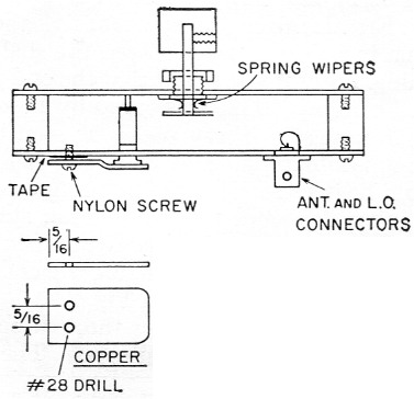
Fig. 1. Cut-away view of the radiai cavity mixer assembly in the 1296 Mc converter.
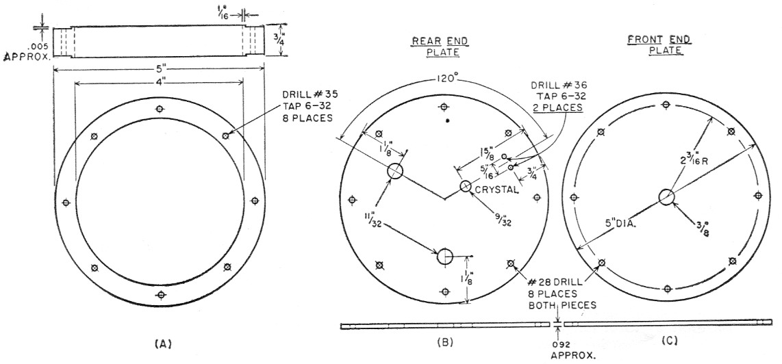
Fig. 2. Dimensions of the principal parts of the radial cavity. Material may be aluminum or brass.
The antenna input, the local oscillator injection and the mixing crystal are all on one face of the mixer, spaced 120 degrees apart. The crystal was mounted somewhat closer to the middle of the cavity than the antenna input connector. This was because the antenna connection on an earlier model was a wire ¾ inch long, from the center conductor of the connector to the opposite end plate of the cavity. Assuming the r.f. input impedance of the crystal to be about 100 to 150 ohm, the crystal would have to be closer to the center than the input tap, for the latter to provide a good match for 50 ohm input. Laboratory tests showed that this arrangement worked out quite well, but the loop coupling gives just as good match. The cavity is loaded quite heavily, as image rejection is no problem. So long as the image rejection is 10 dB or more the over-all noise figure will not be adversely affected. The lower Q reduces insertion loss and lessens the mechanical rigidity requirements of the mixer.
Tuning the mixer is done with a ¼ inch brass shaft passing through the end plate opposite to that containing the mixer crystal and coaxial connectors. A penny-sized copper disk is soldered to the shaft for a capacitor plate, and the shaft runs through a locking-type panel bushing adjusted to provide the necessary friction. In practice the mixer rarely requires tuning, but the red-blooded experimenter would rightfully feel cheated if something were not available for adjusting occasionally.
Spring copper wipers, shown in the drawing, were a refinement that was found to be unnecessary, but it may be just as well to add them anyway. Erratic mixer tuning was at first thought to be due to poor contact between the shaft and its bushing. Later it was found that the end plates were "oil-canning." This was cured by mounting the mixer against a heavy panel, as seen in the rear-view photograph, and changing the end plate to a heavier stock. A further refinement to reduce mixer loss and improve tuning stability was to improve contact between the main body and the end plates by undercutting the end faces of the main body,(2) as shown in Fig. 2A.
The mixing crystal protrudes through one end plate and contacts the opposite one. The large end is insulated by a tight-fitting piece of spaghetti sleeving. The i.f. output is brought off by a copper tab that presses down on the end of the crystal. The tab also serves as a mixer bypass capacitor. It is fastened to the end plate with-two nylon screws, and is insulated from the plate by a strip of plastic electrical tape. (Metal screws, suitably insulated, may be used if the nylon screws are not available.) Because of 40 pF of capacitance to ground so provided, and the relatively low impedance of the circuit, about 400 ohms, there is negligible pickup at the intermediate frequency.
I.F. Preamplifier
As no communications receiver has enough gain to accommodate the low signal level from the mixer, a preamplifier is necessary. Other arrangements might give more gain and lower noise figure than the one shown in Fig. 3, but none would be more simple or readily adjusted. Like the injection string, the i.f. preamplifier is built as a subassembly. Experimentation with other circuits is thus made easy, but in the meantime the builder of the converter is able to receive signals.
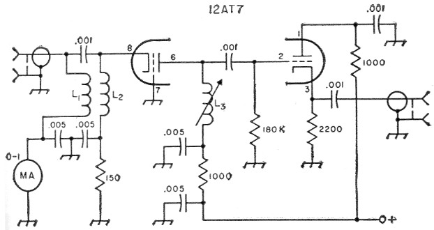
Fig. 3. Schematic diagram of the i.f. preamplifier stage.
L1,L2 Bifilar-wound choke resonating at 16 Mc. 23 double turns No. 26 enamel, ¼ diam., close-wound.
L3 25 turns No. 22 enamel, ½ inch slug-tuned form.
The i.f. amplifier is a 12AT7. The first stage is grounded-grid, and has an input impedance, neglecting input capacitance, of nominally 400 ohms. This happens to be the optimum i.f. impedance for the 1N21-series mixing crystal. The d.c. return for the crystal is through one half of a bifilar r.f. choke winding, the cathode return being the other half. This choke is resonated at the intermediate frequency by the combined effect of the mixer bypass, the coaxial cable and the tube input capacitances. Resonance is checked with a grid-dip meter, removing or adding turns as required. It is not at all critical, as the operating Q is low and the bandwidth consequently is large. Be sure to remove the crystal from the mixer before using the grid-dip meter; otherwise the dip may be questionable.
For maximum gain in the first stage it should be loaded with as low-capacitance and high-impedance a second stage as possible. There should be no tuning capacitance, so a slug-tuned coil is used. The second stage is a cathode follower. This has virtually infinite input resistance, and no Miller-effect capacitance, making the slug-tuned coil the sole frequency-determining element of the preamp. The pass band of the amplifier is very narrow; no more than a few hundred kilocycles. This is not a disadvantage as the coil is quickly adjusted by turning the slug and listening to the noise peak when the receiver is tuned to the desired frequency.
The casual observer may suggest at this point that the cathode follower is useless, as it has no gain and could be replaced by link coupling from the interstage coil. Nothing could be further from correct. A low-impedance link coupled to the interstage coil would load it, and the gain from the grounded-grid stage would drop rapidly. While having a voltage gain of only about 0.9, the cathode follower definitely provides gain compared to the conventional grounded-cathode amplifier. Furthermore, its output impedance is very nearly that of the input of most low- and medium-priced communications receivers.
Oscillator-multiplier chain
One problem in crystal-controlled converters as we progress to higher bands is instability. Having gone to crystal control to achieve stability, we should get as much as crystals will provide. Expensive crystals and ovens could be used, but we would rather do otherwise. Overtone oscillators were also ruled out. Possibly their use would save one stage, but at some sacrifice in stability and only a slight reduction in circuit complexity. Crystal-diode multipliers have merit, but their peculiarities may not be familiar to the h.f. man already experienced in vacuum-tube ultipliers.
As seen in Fig. 4, the injection chain starts with a 10.0 Mc crystal oscillator using the pentode section of a 6U8. Check the frequency before construction progresses too far; if the oscillator is only 8 kc. off, the final injection frequency will be off by more than a megacycle. The 4th harmonic, 40 Mc, is taken from the plate circuit and fed to the triode section of the 6U8, where it is doubled to 80 Mc. Two halves of a 6J6 double twice to 320 Mc. The 320 Mc circuit is balanced, for optimum coupling to the balanced input of the 6J6 push-push doubler to 640 Mc. The 640-Me. plate circuit of this stage is a small loop, parallel-resonant with the 6J6 output capacitance, and tuned by a small variable series capacitor.
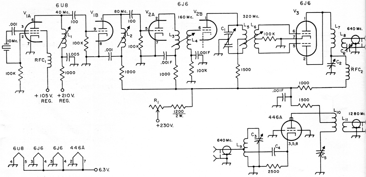
Fig. 4. Schematic diagram and parts information for the oscillator-multiplier chain. Capacitor values below .001 are in pF. Those marked with F are feedthrough type. Resistors ½ watt unless specified.
| C1 | 1.8 to 5.1 pF-per-section split-statcr variable. (Johnson 160-205). |
| C2,C6 | 1.8 pF plastic trimmer (Erie 532). |
| C3,C4 | Part of ASB cavity. |
| C5 | Piston from trimmer capacitor; slides inside end of L10. See Fig. 5. |
| L1 | 18 t. No. 22 on 9/32-inch diam. iron-slug form. |
| L2 | 8 t. No. 22 on 9/32-inch diam. iron-slug form, spaced to 5/8 inch. |
| L3 | 9 t. No. 22, ¼-inch diam., ¾ inch long. |
| L4 | 8 t. like L3. L3 and L4 are side by side ½ inch apart, c. to c. |
| L5 | 3 t. No. 14, 5/16 inch diam., 7/16 inch long, center tapped. Leads 3/8 inch long. |
| L6 | 2 t. No. 22, 1/2-inch diam., 7/16 inch long. |
| L7 | 2 t. No. 14, ¼ inch diam., 7/16 inch long. One 3/8 inch lead. |
| L8 | 2 inch length of No. 16 bent into U shape, ¾ inch wide at open end, ¼ inch at bent end. |
| L9 | Part of ASB cavity. |
| L10 | Final doubler plate circuit; see Fig. 5. |
| RFC1 | 1 mH r.f. choke. |
| RFC2 | 5 t. No. 24 enam. on 1 watt resistor. |
The final doubler is a 2C40 or 446A lighthouse tube, available at most surplus houses for 25 to 50 cents. It uses a modified ASB-5 mixer cavity, also a surplus item. Little use has been found for this unit in the past, though its companion unit, the r.f. amplifier in the ASB-5, is much in demand. Its input circuit will not quite reach 640 Mc in its original form, so it was shortened about ¾ inch by installing a false bottom in the cathode cavity This was made by punching a 1_3/8 inch hole in the middle of the plate cover of the mixer, and slotting the rim in numerous places with a jeweler's saw or coping saw. The cavity is heated on one end only over a gas stove, and the original bottom and cathode conductor temporarily removed. The modified mixer plate cover is slipped over the cathode connector and soldered in place. The works is then reassembled.
The original input hole will then be covered by the false bottom. However, what was originally the ASB local oscillator injection hole is now in the exact position for the 640 Mc drive. Under operating conditions the s.w.r. looking into this doubler was found to be 1.19. A BNC fitting is attached to take the 640 Mc drive.
The 1280 Mc plate circuit is quite simple, and details are more readily conveyed by drawings than by description. The inner conductor is made from /-inch copper fuel line, slotted at the end to receive the plate cap of the 446A. (See Fig. 5.) The insulating bushing, preferably of Teflon, is installed at the other end. The plunger and spring-loaded bearing were taken from a precision piston trimmer found in many pieces of surplus gear. (The ARR-26 has 30 of them.)
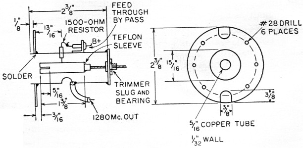
Fig. 5. Details of the 1280 Mc doubler plate circuit. Circular plate fits top of an ASB cavity. See text and photograph. The inner conductor of the line fits over the plate cap of the 2C40 or 446A tube. Output coupling loop can be made from the inner conductor of the coaxial line. Tuning capacitor is made from a piston-type trimmer and its bearing assembly.
The ring attaching the outer conductor to the ASB cavity was cut from flat copper sheet with tin snips. It is held on the end of the ASB cavity and holes are drilled through both it and the cavity. The holes in the cavity are then tapped for 6-32 screws. The outer conductor (brass plumbing pipe) was soldered to the copper ring, and allowed to protrude through it. This makes the outer conductor press firmly against the grid ring of the ASB cavity, giving a good r.f. joint.
The output link enters through a 3A-inch hole, about % inch above the plate cap, as seen in Fig. 5. The B-plus feed resistor enters through a %- inch hole. Its cold side is connected to a feed-through bypass, mounted on a small angle bracket, as close to the hole as possible.Power supply
The d.c. output voltage of the power supply is about 230. Two 0B2 regulator tubes in series provide regulated 210 volts for the oscillator plate and 105 for the oscillator screen. Other stages of the injection chain are run from the unregulated output of the supply, through a 2000 ohm wire-wound potentiometer. This is useful for varying the injection electrically. It will be found that crystal currents from 50 to 500 microamperes have very little effect on the mixer operation.
The i.f. preamplifier is also operated from the unregulated supply. It will be seen from Fig. 4 that the oscillator voltage is left on continuously during transmit or standby periods. This keep-alive voltage eliminates the last few cycles of drift when going from transmit to receive. Stability, both long and short term, was found to be worth the effort when we began to make straight c.w. contacts on 1296 Mc. Stability and c.w. notes were like 80 meters - a vast improvement over several previous converters used on this band. Being able to set up the receiver on a frequency precisely, and then just wait for the signal to come through, has been an important factor in several DX attempts on 1296 Mc.
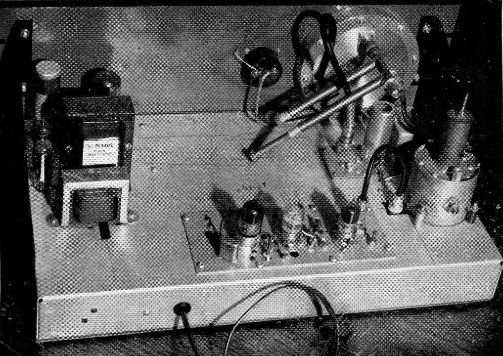
Rear view of the 1296 Mc crystal-controlled converter. At the back of the chassis is the injection string assembly, except for the 1280 Mc doubler, which is at the far right. The small assembly adjacent to the doubler is the 16 Mc i.f. preamplifier. The radial mixer cavity is fastened to the front panel. Power-supply components are at the left.
Improvements
After the first signal is copied on the converter, ideas will come along for possible improvements. With the subassembly construction employed ideas can be tried one at a time, with the assurance that unchanged other units will continue to operate properly. A pi-network input to the i.f. preamplifier may aid materially in matching the crystal to the grounded-grid amplifier input. This can be done by adjusting different combinations while listening to a fairly weak signal. The ninth harmonic of a 144 Mc transmitter can be used as a signal source, though a silicon diode or vacuum-tube noise generator may give better results.
Cascode and pentode preamplifier circuits can be explored. Two problems to be expected will be instability and matching the input impedance of the amplifier. Keep in mind that mere absence of oscillation in an amplifier does not guarantee that it is free of regeneration, and consequent poor noise figure.
Adequate injection was obtained with the setup described, but some experimenters may experience trouble due to variation in lighthouse tube condition. Many 446A and 2C40 tubes obtained on the surplus market are inferior in one way or another. Nearly all have been removed from equipment, even when they are advertised as "new."
While the 3A-inch signal injection loop seems to work well there is no assurance at this point that some other size loop or different coupling method would not be better. Untuned mixers deserve consideration. Some experimenters report poor results with these, possibly because of mismatched antenna or feedline impedances. Poor mixer performance may also result from much of the signal being shunted into the local oscillator chain, where it is dissipated. High-Q tank circuit design for the injection chain output stage may be helpful here, a point that is often overlooked in 420-Mc. crystal-mixer converters, as well. The untuned mixer has the advantage that the signal may be injected at 640 or 427 Mc. with only slightly degraded performance.
In spite of the fact that most u.h.f. triodes are not supposed to work well at 1300 Mc, several experimenters have used 446 As, pencil triodes and the 416B with gratifying results. The apparent improved performance may be due to a poorly-constructed or improperly-adjusted mixer, benefiting greatly from the gain of the r.f. amplifier. The 416B, particularly, was designed for commercial applications at 4000 Mc., so it should be good at 1300 Mc when properly handled. Poor noise figures quoted for this tube are from data intended for wide-band applications. By proper cavity design the bandwidth can be kept low in amateur applications, and improved noise figures might result.
A good ready-made r.f. amplifier is the ASB-5 (CPR-46-ACJ) r.f. cavity. This was originally intended for use in the 500 Mc region. Both input and output cavities will tune to 1300 Mc as three-quarter wave lines. This cavity uses the 446A tube, but adapter rings have been constructed to permit the use of the 416B. The ASB-7 cavity is also useful. In many ways, this unit is more flexible than the former, and more circuit adaptations become apparent during its use. Fairly successful attempts have been made in other directions also. One such amplifier used a 6BY4 ceramic u.h.f. receiving triode on 1200 Mc. As nearly as could be determined, this tube performed as well as a 416B known to be operating properly.
Crystal mixer diodes come in a variety of types. The most common ones are the 1N21 and 1N23 series. These have been made in suffixes ranging through the letter "E." The 1N21 series is intended for use from 1000 to 3000 Mc. It will work higher. The 1N23 is intended for use from 3000 to 10,000 Mc, and will work lower. As long as a mixer is operating poorly, or only fairly well, there is virtually no difference in the performance of any of these crystals. It is when a really effective mixer is coupled with an i.f. preamp of 1 to 3 dB noise figure that the amazing difference between 1N21A and the 1N21E becomes evident.
Newer crystals such as the MA421 give noise figures of 6 dB and better in standard test setups. Individually-tailored amateur circuits can be expected to perform even better. Because of semiconductor progress, both in mixers and amplifiers, the vacuum-tube r.f. amplifier at 1200 Mc appears less desirable than ever.
The rectified crystal current flowing as a result of the local oscillator injection should be measured with a milliammeter having as low a d.c. resistance as possible. Degraded performance may result from the d.c. bias developed across this resistance. The experimenter is invited to try the use of small amounts of back bias on the crystal to improve performance.
Notes
- Robertson, "A tripler for the 1215 Mc band," QST, July, 1955, p. 20.
Cross and Taft, "A practical front end for a 1215 Mc receiver," CQ, January, 1958, p. 43. - Cavities are available in the form shown in Fig. 2 from Mooradian Machine Works, 1752 E. 23rd St., Los Angeles. Price, $1.50 each.
Donald K. Goshay, W6MMU.