Additions to the 250 Series Matchboxes
The original models of the Viking Matchboxes (250 series) provided all the tuning and switching controls that are necessary in an "antenna coupler," but had no built-in indicators for telling the operator when he had the right adjustments; for best results, an external s.w.r. bridge was a recommended accessory. The earlier 250 watt and kilowatt Matchboxes have now been supplemented by units, otherwise similar to their predecessors, which are equipped with reflectometers so proper matching adjustments can be attained with a minimum of trouble. The kilowatt version carries the type number 250-30-3 and the smaller (now rated at 275 watt) is type 250-23-3.
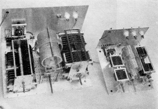
Interiors of the kilowatt (left) and 275- watt Matchboxes. The differential capacitors are at the right in each case. The L-shaped chassis forms the bock and bottom of the cabinet, thus the shafts shown pointing downward here project through the front panel when assembled. The panel and remaining box sides are a single unit.
Except for the addition of a meter and two small control knobs for the reflectometer circuit, the external appearance of the panels is the same as in the older models. In fact, there is also very little change evident in the internals of the Matchboxes since the reflectometer is an external unit which can be installed at any convenient spot in the coax line whose s.w.r. is to be checked. D.c. connections between the reflectometer and the coupler are made through a two-conductor shielded cable. The meter has a 0-100 microampere movement. One of the panel controls is for adjusting the reflectometer sensitivity and the other is for switching from reflected to forward readings.
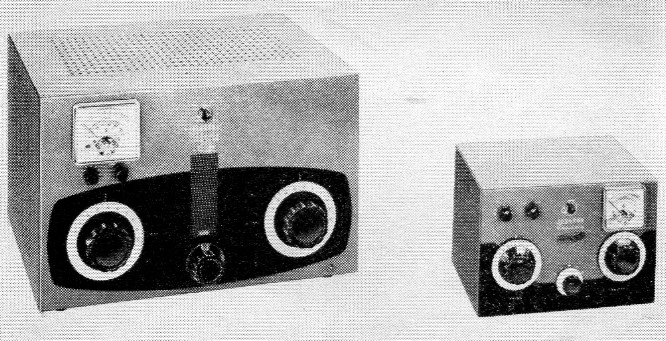
New models of the E. F. Johnson Co. Viking Matchboxes differ from the older ones in having reflectometer indicators and controls on the front panels.
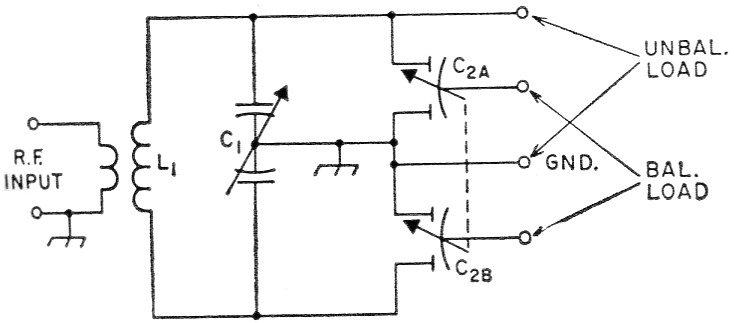
Fig. 1. Basic circuit of the Matchbox, with accessory details in the actual equipment omitted. The circuit provides variable coupling, and thus impedance matching between a coax line connected to the input link and a load connected to the terminals at the right, by adjustment of the differential capacitor C2. Circuit resonance is maintained by C1, after proper choice of inductance at L1.
If you haven't previously met the Matchbox, it is a completely bandswitched matching circuit covering the amateur bands from 3.5 through 30 Mc. It will match 52 ohm coax to balanced-line loads ranging from 25 to 1500 ohm, and to unbalanced loads of 25 to 3000 ohm, in the 275 watt model; and 50 to 1200 ohms balanced, 50 to 2000 ohms unbalanced, in the kilowatt model.
The basic circuit is a parallel-tuned network including a dual differential capacitor, C2, which operates as a variable capacitive voltage divider to accomplish matching, much in the same way that taps on the tank coil do in the conventional coupler circuit. The capacitive adjustment is of course smoother and more convenient, although physical limitations of capacitors place more of a restriction on the matching range than is the case with coil taps. Because of its differential construction O has relatively little effect on the tuning of the system, this being the function of C1, a balanced capacitor of orthodox construction. (Incidentally, you won't find capacitors like C2 in the catalogs; the ones used in the Matchboxes are made especially for these units.)
The new models retain all the features of the earlier units, such as built-in antenna changeover relay, and terminals for an r.f. probe connection. Dimensions also remain the same 9_7/8 long by 7 inches high by 10½ inch deep in the 275 watt model, 17¼ by 10_7/8 by 12_1/8 in the kilowatt version.