The Perseids powerhouse
A cool Colorado kilowatt for 50 and 144 Mc, without coil switching or changing.
For the uninitiated let's start out by explaining that the Perseid Meteor Shower in August provides a propagation medium for 144 Mc signals over distances that are extremely difficult to work by any other means.(1) This opportunity is best exploited with high power, and the amplifier to be described did a fine job for the writer in the two Perseid showers. Seven new states were worked, including one over a 1240-mile path.(2) The transmitter has done well on 50 Mc also. It was the means by which the sixth and final continent (Asia, JA8AO) was worked for the writer's 50 Mc WAC, in November, 1958. The amplifier features reasonably straightforward design using standard parts, and building it does not require a home machine shop or a sheet-metal factory.
Multiband transmitters have been taken for granted by amateurs for so many years that many occupants of our lower bands have hardly heard of a transmitter that will operate on only one band. The multiband rig is still rare in the v.h.f. field, however, though progress is being made in the design of setups for two or more bands through the use of coil changing or switching. Recently a commercially-available transmitter was described in which the plate circuit was designed for operation on both 50 and 144 Mc. without the requirement of coil changing of any kind.(3)
Building upon the two-band tank circuit idea used in the plate circuit of the Johnson 6N2, the author set out to construct a high-powered amplifier using the circuit design in both the grid and plate circuits, so that no switching or coil changing would be needed to cover both these popular v.h.f. bands. Though more than a year was spent in the design, construction and testing of the amplifier, the results have been most gratifying, and well worth the effort.
The key to the high efficiency of the amplifier lies in the transmitting tubes now available, which were designed especially for v.h.f. service. The Eimac 4X250B tubes used do a fine job at 144 Mc, as well as 50, and their cost is not out of reason in these days of liberal amateur budgets. Though it is possible that slightly higher efficiency might be obtainable in a single-band design, the results achieved with this rather unusual amplifier have shown that the difference would hardly be discernible on the receiving station's S meter.
Essentially, the Perseids Powerhouse is a push-pull amplifier, cross neutralized, with its own bias supply built in. Provisions are made for Class C c.w. or a.m., and for Class AB1 linear amplifier service. A front-panel control switches the mode of operation, and a tune-operate switch sets up safe operating conditions for tune-up. Provision is made for external metering of the total grid current to both tubes, each tube's screen current, and the r.f. output on both 50 and 144 Mc. An external 0-1 milliammeter takes care of these functions. Another external meter should be connected in the high-voltage lead for plate-current measurement. If the input approaches the kilowatt level a voltmeter should also be provided, to determine the plate power accurately, as required by FCC regulations.
The two-band tank circuits
There is no magic or undue complication about the means by which the grid and plate ircuits are made to work on both bands without switching. Both are half-wave lines at 144 Mc, with the tubes at one end and the tuning capacitance at the other. Both ends of a halfwave line used in this way exhibit high impedance, but at some point in between the impedance is very low. If the tank circuit were used for 144 Mc only, the bias or plate-voltage connection would be made at this point of zero r.f. voltage, through r.f. chokes. Actually, anything except a direct short can be connected there and it will have no effect on the functioning of the circuit at the resonant frequency. Thus it is possible to connect a 50 Mc coil and, with a little care, set up the circuit so that it is capable of tuning to both 50 and 144 Mc with practically the same efficiency as would be possible for either frequency by itself. The 50 Mc circuit so connected works as a conventional coil- and-capacitor tank, the 144 Mc line merely appearing as added lead inductance at the lower frequency. Methods for locating the low-voltage point on a half-wave line have been described in the ARRL Handbook, and in several QST articles, the most recent being one by W1VLH.4 His method was used here, as it is most convenient for shielded lines.
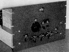
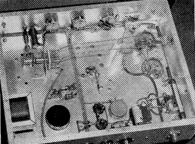
The Perseids Powerhouse, a 1 kW amplifier for 50 and 144 Mc. Method of shielding the r.f. portion of the amplifier is visible at the left. Two chassis are used, butting together, with a "weather-stripping" of perforated aluminum covering the joint edges.
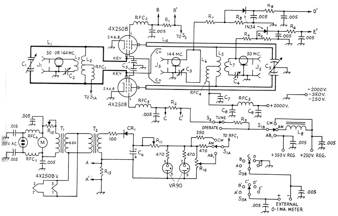
Fig. 1. Schematic diagram and parts information for the 2 band v.h.f. amplifier. Capacitors not described are 5 nF disk ceramic.
| C1 | 50 pF-per-section butterfly variable (Hammarlund BFC-25). Remove two stator and two rotor plates. |
| C2 | 50 pF variable (Hammarlund MC-50-5). |
| C3 | 35 pF variable, double-spaced (Hammarlund MC35-SX). |
| C4 | 50 pF variable, double-spaced (Hammarlund MC50-SX). |
| C5 | 50 pF-per-section transmitting butterfly variable (B & W JCX-50-E). |
| C6 | 10 µF 150 volt electrolytic. |
| C7,C8,C9 | 1 nF disk ceramic, 3000 volt. |
| Cn | Neutralizing wires; see text and photo. |
| Cs | Screen bypass capacitor built into Eimac 4X150A4010 socket. New version is SK-610. |
| L1 | Half-wave grid line-No. 12 wire. Sides 1¼ inches apart. See Fig. 2 and photo. |
| L2 | 50 Mc grid coil 6 t. No. 12 wire, ¾ inch diam., spaced diam. of wire, except at center. See text and photo. |
| L3 Combination coupling coil and loop No. 12 wire, 1 t. at center of L2, with leads adjacent to L1. See text and photo. | |
| L4 | 144 Mc. plate line 1 × 1/16 inch copper strap, See Fig. 2 and photo. Note slotted holes for mounting L5. |
| L5 | 50 Mc plate coil 4 t. No. 8 copper, 1¼ inch diam., spaced diam. of wire, except at center. See text and photo. |
| L6 | 144 Mc coupling loop No. 12 wire bent into V, 1½ inch wide and 5¾ inch long. See text and photo. |
| L7 | 50 Mc coupling loop 1 t. No. 12 wire, 1½ inch diam., at center of L5. Keep at least ¼ inch from any part of L5. See text and photo. |
| L8 | 10 H 110 mA filter choke (Stancor C-1001). |
| M | 100 c.f.m. blower, 115 V a.c. (Burstein-Appleby 4A195). |
| R1,R2,R13 | Meter shunts-adjust to read full scale at 100 mA. |
| R3 | 4000 ohm, 10 watt, wire-wound. |
| R4,R7 | 15,000 ohm, 4 watts (two 30,000 ohm 2 watt carbon resistors in parallel). See text for location. |
| R5,R8 | 300 ohm, 1 watt, carbon. |
| R6,R9 | 12,000 ohm, 2 watt, carbon. |
| R10 | 100 ohm, 25 watt, adjustable. |
| R11 | 2500 ohm, 10 watt, adjustable. |
| R12 | 50,000 ohm 4 watt wire-wound potentiometer. |
| RFC1 | 7 µH v.h.f. choke (Ohmite Z-50). |
| RFC2,RFC3,RFC4,RFC5 | 4 µH v.h.f. choke (National R-60). |
| RFC6,RFC7 | 20 t. No. 18 enam. 4 inch diam., close-wound. |
| S1 | 2 pole 3 position rotary switch, non-shorting. |
| S2 | 1 pole 3 position rotary switch, nonshorting. |
| S3 | 2 pole 5 position rotary switch, nonshorting. |
| T1 | Filament transformer, 6.3 volts, 8 amp. |
| T2 | Filament transformer, 6.3 volts, 1 amp. |
Though the low-voltage point is the electrical midpoint of a half-wave line, if a tube is connected at one end the point will not be at the physical center of the line ordinarily. The drawings and photographs show the approximate positions for connection of the 50 Mc coils. Precise adjustment of the connection point can be done after the amplifier is assembled.
When the plate circuit was in the design (cut and try!) stage it was obvious that a half-wave line for 144 Mc would have to be bent in order to fit in the space available with standard relay rack mounting. The author started out bravely with two lengths of 5/8 inch copper tubing and a tubing bender, but our advice is, if you have never worked with this vicious stuff, don't! Copper tubing may well have a higher Q and work more efficiently than the strap used here, but if you can't bend it to fit the space available there's no point in having it. A local wholesale hardware house had 1/16 inch thick 1 inch flat copper strap, which is perfect for this work. It bends easily, yet is quite rigid when formed into the desired shape. We had no way of comparing tube and strap tank circuits, but the latter works very well in this amplifier. Dimensions of the plate and grid lines and coils are given in Fig. 2.
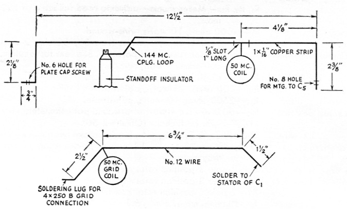
Fig. 2. Dimensions of the halfwave grid and plate lines used in the W0IC amplifier. Sides of plate line are 3_1/8 inches apart, center to center. Grid line wires are 1¼ inch spaced. Points for connection of 50 Mc coils are approximate. See text for instructions for adjustment.
Construction
The amplifier is built on a 17 by 12 by 4 inch aluminum chassis, to which is attached a standard aluminum rack panel measuring 19 by 12¼ inches. The shielded enclosure for the plate tank circuit mounted on top of the chassis base just behind the front panel consists of two 17 by 8 by 3 inch aluminum chassis. The bottom one is mounted open end up and the top one serves as a cover to complete the top of the shield. The seam between the two chassis is covered by a piece of Reynolds perforated aluminum sheet about 3¼ inches in width which is fastened to the sides and the back of the lower chassis with self-tapping screws. Although the perforated sheet does not cover the front of the two chassis behind the front panel, very little r.f. seems to escape. Four 5/8 inch holes are cut in the top shield chassis over each 4X250B tube for cooling air stream passage.
Throughout this discussion, the main chassis will be described from a rear view, and the location of parts to the left or to the right side of the chassis will be from a rear view. Viewed from the top, the tube sockets are mounted inside the shield enclosure and extend through the base chassis with their centers about 3_1/8 inch apart and about 2_3/8 inch from the left side of the shield enclosure. In order to have each plate line positioned the same distance from the sides of the shield cover, the centers of the sockets should be approximately 2_3/8 inch from the front and rear of the enclosure. These dimensions do not appear to be critical, but care should be used to make sure that the socket holes cut in the bottom shield chassis match accurately with the holes cut in the large base chassis. If the Eimac type 4000 socket is used, all four cathode pins should be permanently connected to the socket skirt by means of 4-40 machine screws.(4) The type 4010 socket, which is made with the cathode pins grounded, is to be preferred.
The neutralizing leads are No. 12 wires about 1¼ inches long, bolted to small ceramic feed-through insulators mounted about 5/8 inch apart and 3 inches from the left end of the shield enclosure. This places each feed-through approximately 1¾ inches from the center of the associated tube socket. Adjustment of the neutralization is made by bending the wires toward or away from the anode cooler of each 4X250B.
Neutralizing is discussed in detail later in this article. A trick is borrowed from a commercial design,(5) and a shield of copper flashing about one inch wide is mounted on soldering lugs attached to the tube socket mounting screws, as shown in the photographs. This effectively shields the neutralizing wires from the screen grid rings of the 41250B tubes, which are exposed above the socket bases. It may be impossible to neutralize the amplifier if the neutralizing wires feed back to the screen grid rings as well as the plate terminals.
Heat radiating plate connectors are used, and the plate lines are fastened to the top of these connectors by means of the tapped hole provided.
Top view of the 2 band amplifier, with cover removed. Halfwave line at 144 Mc made from 1 inch wide copper strap has 50 Mc coil connected at its low-impedance point.
144 Mc output coupling circuit
The principal difficulty in the adjustment of the Perseids Powerhouse occurred with the output link circuits. First attempts were made to have one output link handle both 6 and 2 meter, a, is done in the grid circuit. A number of different sizes and shapes of dual links were tried, but none of them would work on both bands properly. Accordingly, the dual output coupling circuit was worked out. First, two separate output coupling links tuned by a single loading capacitor and feeding into one coax output receptacle were tried without success. Separate coax receptacles for both bands were then tried for each band, with the links tuned by a common capacitor, but still correct loading could not be accomplished on each band without the adjustment of one affecting the other. Finally, entirely separate output circuits for each band, using separate links, loading capacitors and output connectors were installed and success was achieved. However, there is still some interaction which must be watched in tuning.
The standoff insulators for holding the 144 Mc output coupling loop are approximately 4_3/8 inch high, including the metal mounting hardware on top. They are mounted approximately 6¾ inch from the left side of the enclosure, about 14 inches apart. The open ends of the loop are bolted to the standoff insulators the tops of which are approximately one-half inch below the plate lines. To clear the 6 meter coil, the open ends of the link are bent to leave the standoffs at an angle of 45 degree until the main body of the loop is parallel to and slightly higher than the plate lines, as shown in the photograph. From the front standoff, a copper flashing strap ¾ inch wide and 3¾ inch long runs to the stator of the 144 Mc antenna loading condenser. A similar strap 5½ inch long connects the other end of the link to the 144 Mc output coax receptacle.
50 Mc plate circuit
The 50 Mc coil is approximately 1¼ inches long, with the middle turns spread apart to leave a 3/8 inch space for insertion of the output coupling link. The ends of the coil are sweated to heavy soldering lugs. One inch long slots about 3 inch wide were cut in the plate tank lines to allow the 50 Mc coil to be positioned at the exact null. The coil lugs are bolted in place by No. 6 machine screws. The approximate position of the 50 Mc coil is indicated in Fig. 2, but the exact point of the null must be determined after the entire amplifier is completed. Plate voltage is fed through to the center of this coil for both bands.
An important point in the design of the 50 Mc coil is to make sure that resonance occurs sufficiently far removed from the setting of C5 that tunes the line from 150 to 160 Mc. When the amplifier is being driven at 50 Mc, considerable output can be obtained at 150 Mc if the plate circuit tunes to both frequencies simultaneously. Proper design of the 50 Mc coil will separate these resonance points so that there will be no danger that harmonically related frequencies will occur at the same setting of the plate tuning capacitor. Similar considerations govern the design of the grid tank circuit. Ideally, the plate circuit should just hit the highest expected operating frequency in the 2 meter band with the tuning capacitor at minimum.
The 50 Mc output link is larger than the 50 Mc coil, so part of it remains outside the coil. One end of the link goes direct to the stator terminal of the output loading capacitor. The other lead runs to a 2 inch standoff insulator from which a copper strap approximately ¾ inch wide and 3¼ inches long completes the circuit to the output coaxial fitting for 50 Mc.
The tuning capacitor for the plate circuit, C5, is a heavy-duty butterfly type, mounted directly to the chassis, thus grounding the rotor. The rear frame of the capacitor is mounted approximately 2% inches from the right end of the shield enclosure, but the exact spot of mounting should await the attachment of the plate lines. The capacitor is then positioned so that no strain will be placed upon the lines and the tubes. The use of a National RAD right-angle drive permits the plate tuning capacitor to be mounted symmetrically with respect to the lines. Some backlash is introduced in tuning, but little difficulty has been experienced with this. A small hole is drilled in the top center of the front frame of the tuning capacitor for mounting a 5/8 inch ceramic standoff insulator, to carry the r.f. choke connected to the center of the 6 meter coil, and the shielded high voltage lead to the r.f. choke.
More symmetrical spacing of the two tuning capacitors and the drive shaft for the plate tuning capacitor could be devised. Their rather close spacing is the result of the 50 Mc loading capacitor having been added after the original layout work.
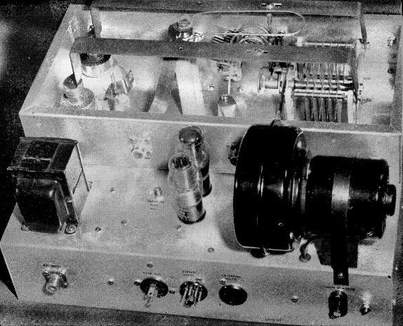
The filament transformer is mounted at the lower left, on the base chassis. Above and to the right is the 144 Mc coax output receptacle, approximately 5½ inches from the left side of the shield enclosure and about 1½ inches above the base chassis. The 50 Mc output receptacle is 10 inches from the left side of the shield enclosure, and again this arrangement resulted from the subsequent need for a separate output connector for 50 Mc. The two VR tube sockets are approximately 8 inches from the left side of the base chassis, and the 50,000 ohm Class AB1 bias potentiometer is mounted an inch or so to their left. The blower, right, posed a mounting problem be cause no mounting flanges were provided. This was solved by cutting a half circle in a small piece of 2 × 4 inch pine block the diameter of the motor housing. A hole was cut in the base chassis of sufficient size to accommodate the blower output tube, and the motor housing resting on the wood base was fastened to the chassis by a light steel strap, as shown in the photograph.
On the rear lip of the base chassis there are mounted, from left to right, the r.f. input coax receptacle, the 110 volt a.c. input receptacle, the screen voltage plug, the external meter socket, the high-voltage connector and a ground connection. The spacing of these items is not critical; they should be spaced to suit the internal wiring arrangements.
Bottom view of the WQIC v.h.f. amplifier, with cover removed. On the front panel are the grid-tuning drive shaft, the mode switch, tune-operate switch, meter switch, and grid loading adjustment. The halfwave grid line occupies most of the upper portion of this view, with the tube socket at the left. In the foreground may be seen the screen modulation choke, the air intake, VR tube sockets, potentiometer and other biassupply components.
Grid tank circuit
Now let us turn to the underside of the chassis, and the location of the components as viewed from the rear of the chassis. The grid tank circuit is similar to the plate tank circuit, but because of the lower power handling requirements, No. 12 wire is used. Fig. 2 gives the dimensions of the grid line. It will be noted that the 50 Mc coil is connected much closer to the tube end of the line than is done on the plate line. This is because of the high grid-to-cathode capacitance of the 4X250B tubes and indicates graphically that the electrical quarter-wave point varies with the capacitance at the tube end of a half-wave line. As with the plate tank, care should he taken that fundamental and harmonic resonances do not occur at the same point of the grid tuning condenser. The tuning capacitor, C1, is a butterfly type, mounted on an aluminum angle with the. rotor insulated from ground. Again, a right-angle drive is used, which introduces some backlash, but two rotor and two stator plates are removed, to keep the tuning rate down. Each plate is removed by grasping it with long-nosed pliers and gently bending it back and forth until it loosens from the soldered position.
The grid input-coupling link is a U-shaped affair mounted on 2 inch standoff insulators. The vertical end portions are about 5/8 inch high, and the horizontal sides parallel the grid lines for about 1 inch. Instead of being a closed U at the end, the link is bent into a one-turn loop about ¾ inch in diameter. This is covered with spaghetti and inserted inside the 50 Mc coil, to provide the pickup link for that band. The parallel sides of the tank couple to the 144 Mc line. RG-58/U coax from the r.f. input receptacle runs to one end of the link, and No. 12 wire connects the other end to the stator terminal of the grid loading capacitor. The 50 Mc grid coil has 6 turns of No. 12 wire approximately ¾ inch in diameter and 1 inch in length. The center turns are spread about a quarter of an inch, for the 50 Mc coupling link. Little difficulty was experienced with this coupling arrangement; the series capacitor, C2, may be used to vary the grid drive quite effectively on both bands.
Underchassis wiring
At the front left will be seen the screen-dropping resistor, R12, which is inserted in the screen lead when the tune-operate switch is in the tune position. For experimental purposes a third position was wired into this circuit which grounds the screens, but this was never used in actual operation. The most critical item in tuning is the screen current. Improper loading or drive can run the screen current to very high values, which if allowed to continue for any length of time will damage the tube. The 3900-ohm resistor in the screen lead effectively protects the screens against overcurrent. The screen current will not become excessive when the plate voltage is completely removed. However, it is not recommended that the tubes ever be operated with the screen voltage applied and the plate voltage removed.
From left to right at the bottom of the front panel, viewed from the rear, can be seen the mode switch, the tune-operate switch, and the meter switch, with the meter shunt resistors mounted directly on it. Shielded wire is used for all leads which leave the chassis, and in the heater circuits of the 4X250B tubes. At the lower left can be seen the screen modulation choke and to its right the air duct from the blower. It was thought for a while that perhaps a copper screen should be placed over the air duct to eliminate the escape of r.f. energy, but this has not become necessary at the author's operating location.
In front of the air duct are the parts comprising the 50 Mc r.f. voltmeter. Above and to the right are the 144 Mc r.f. voltmeter components. It will be noted that all the parts for the 50 Mc r.f. voltmeter are located underneath the chassis, whereas only the diode and the output filtering circuit of the 144 Mc r.f. voltmeter are similarly situated. It was found that when the voltage-divider (R4 and R5) portion of the 50 Mc r.f. voltmeter was located in the shielded enclosure containing the plate lines maximum r.f. voltage indication did not coincide with the maximum r.f. output to the antenna transmission line. This effect was not noticed on the higher band, so the 144 Mc voltage divider resistors (R7 and Rs) were left in the plate circuit compartment and the diode and filtering components placed below the chassis. The r.f. connection is made at the coaxial socket in both places.
At the lower right is a heavy duty adjustable resistor, R10, which is in the primary circuit of the filament transformer. SpeciQications for the 4X250B tube call for 6.0 volt oil the heater. This resistor is adjusted to give the proper operating voltage at the tubes, under operating conditions.
The bias circuit is quite similar to that in Southworth's single 4X250B amplifier,4 but because two amplifier tubes are used it was necessary to use two VR90 tubes in parallel to handle the maximum grid current. This may run as high as 64 milliamperes in a Class C operating condition. The 470-ohm resistors in the anode leads equalize the voltage drop across the VR tubes. The dropping resistor, Rn, ahead of the VR tubes should be adjusted to the point where the voltage applied is slightly higher than is needed for them to fire. Drive applied to the grids of the 4X250Bs will cause an increase in the voltage applied to the VR tubes, which will be effectively regulated by the VR tube action. The adjustment of the dropping resistor is just the opposite of that in a screen circuit for instance, where additional current will be drawn from the supply when drive is applied. For proper screen voltage regulation, the VR tube dropping resistor is adjusted to give maximum permissible current to the VR tube rather than minimum.
On the rear apron of the chassis (not visible in the photograph), the r.f. filtering chokes and capacitors are all mounted as closely as possible to the sockets and connectors to provide maximum r.f. filtering. Standard TVI precautions, including bypassing and shielded wire, are used on all leads leaving the chassis and no harmonic type TVI has been observed from the operation of the Perseids Powerhouse.
Setting up the two-band circuits
After both plate and grid lines have been installed with their associated tuning capacitors and the tubes placed in their sockets, a temporary hairpin-shaped link should be coupled fairly closely to the lines. A length of coax with a one-turn loop at the end should be coupled loosely to the coil of a grid-dip meter and connected to the 144 Mc output fitting. Tune the g.d.o. to the approximate frequency of operation, in this case 144 to 145 Mc. The tuning capacitor should now be rotated until resonance is indicated by the grid-dip meter. The lead point of a wooden pencil should be touched to various places along one of the lines and the deflection on the grid-dip meter noted. It will be seen to be large when the pencil is touched to the plate terminal of the tube and it will diminish as the pencil is run down the line toward the point where the 50 Mc coil is connected. It will rise again as the pencil point is moved toward the tuning capacitor. Somewhere along the line there will be found a point where the deflection is quite small or nonexistent. The 6 meter coil should be connected across the line at this point.
In the case of the grid circuit, the quarter-wave point was located without placing the bottom shield cover in position, and this has proved to be satisfactory for all practical purposes. However, in the case of the plate tank it was found that placing the top shield cover in position made a substantial difference in resonant frequency of the plate tank, so it was necessary to determine the quarter-wave point with the top shield cover in place. This required the drilling of a hole at the point which had been determined to be the approximate quarter-wave point with the top shield removed. Then a pencil can be inserted through this hole and the exact quarter-wave point noted. If a standard size hole is drilled in the shield, a regular metal plug insert can be placed in the hole after the exact connection point has been determined.
Operation
If the grid and plate tank circuits have been carefully checked with the grid-dip meter prior to actual operation to see that they will tune to both 50 and 144 Mc. at different places on the dial as was previously mentioned, no trouble should be experienced in placing this amplifier in operation. Grid drive should be applied and the grid circuit tuned for the maximum grid current prior to the application of the screen and plate voltages. Detune the series capacitor, C2, if the current is too high. Reduced plate and screen voltages can be applied with the tune-operate switch in the tune position, and the plate tuning and loading capacitors adjusted to give maximum output, as measured on the output voltmeter circuit. Be sure that the proper coax output receptacle is used, as very little output will be obtained from the 144-Mc. output circuit when the amplifier is tuned to 50 Mc., and vice versa. At the author's station, separate antenna relays are used for 50 and 144 Mc., and coax cables are run from both output receptacles to their respective relays at all times. Both antenna relays should be activated in the transmit position when transmitting on either band. This will protect the receiver on the band not in use.
When the amplifier was originally constructed, no provision was made for neutralization, but it was soon discovered that oscillation occurred in the vicinity of 50 to 60 Mc when plate and grid circuits were tuned to this region. Fortunately, the addition of the cross-neutralizing wires took only a short time, and the performance of the amplifier improved greatly. The best setting of the neutralizing wires can be determined by the plate-current grid-current method frequently used in commercial transmitters. Set the amplifier up on 50 Mc, working into a dummy load. Tune to the plate-current dip at resonance (not necessarily maximum output). If the grid current increases on the high-capacity side of plate-circuit resonance, the neutralizing capacitance is too high. If the opposite occurs (grid current incrdhses on the low-capacity side of plate-circuit resonance), there is too little neutralizing capacitance.
When the amplifier is properly neutralized, grid current should not change, or should peak, as the plate circuit is tuned through resonance. Checking the neutralizing adjustment can only be done with the top shield cover in place, but it is no trick at all to neutralize the amplifier in a few minutes after you get the hang of it. A dummy load should be connected to the output 50 Mc coax receptacle, and the exciter should be furnishing normal drive. (CAUTION - Remove all high voltages from the amplifier before removing the top shield cover and making adjustments.) Also, the amplifier should not be operated off resonance more than a few seconds. The only oscillation was in the 50 Mc range and adjustment at that frequency sufficed for 144 Mc. When properly neutralized and with normal output loading, the amplifier is completely stable even in the Class AB1 operating position with 350 volts on the screens and the plates drawing 200 milliamperes static current at 2000 volt.
No parasitics were encountered in the development of the Powerhouse. The excellent screen bypassing characteristics of the Eimac sockets undoubtedly contribute to the stability of the amplifier. If parasitics should occur, a good place to start would be to try the method used in the Johnson 6N2. A 2 watt 47 ohm resistor is tapped along each plate line for approximately one inch at the plate end of each line. In particularly difficult cases, similar treatment might be tried on the grid lines. In any event, here's hoping you have as much luck as the author in this depart.. ment.
Power supplies and drive requirements
The 4X250B tubes can be operated efficiently at plate voltages from 500 to 2000. However, slightly more drive and considerably more screen current is required at the lower voltages. About the best way to obtain maximum efficiency for any given plate voltages is to adjust drive, screen voltage and output loading for maximum r.f. output as measured on the output voltmeter, keeping a weather eye on the screen voltage and screen and plate currents. A very important protective device is a screen overload relay set to cut out at no more than 100 milliamperes total. Excessive plate current can be tolerated for short periods of time, but the screens can't take it and need quick protection at all times. The Powerhouse runs Class C narrow-band phase modulation with a full kilowatt input easily (2000 volts at 500 mA, 250 volt on the screens) on both 50 and 144 Mc. Considerably more than enough drive is obtained from a Johnson 6N2 operating at reduced input. If marginal drive is available, some experimenting with the grid coupling link might be desirable, to give better coupling efficiency, particularly at 144 Mc Class AB1 operation on 50 Mc s.s.b. has been quite satisfactory. Operating conditions specified by Eimac are 350 volt regulated on the screen, and 200 milliampere static plate current. The latter adjustment is made by setting R12 for the proper plate current without r.f. drive. Plate modulation has not been attempted, though a position is provided for it on S1A. The maximum allowable plate voltage when operating in this condition is 1500.
The author is indebted to Ed Tilton, W1HDQ, for a considerable amount of advice and asaitstance and, in particular, for his work in taming the beast during preliminary tests. When the amplifier was first constructed, the rotor of the grid tuning capacitor was grounded. Ed was able to eliminate oscillation in the amplifier in the 50-60-Mc. region only by isolating the rotor from ground. Some adjustment of the length of the grid lines improved stability in this region also.
Notes
- Bain, "V.H.F. meteor scatter propagation," QST, April, 1957.
- "The world above 50 Mc," QST, October, 1958 and 1959.
- "The viking 6N2 transmitter," Recent equipment, QST, March, 1957.
- Southworth, "Using the 4X250B on 144, 220, and 432 Mc.," QST, February, 1957.
- "The Amplex KW-62 Amplifier," Recent Equipment, QST, July, 1958
Claude M. Maer, Jr., W0IC.