Possible errors in V.S.W.R. measurement
Effect of directivity in the measuring device.
The importance of exact balance in an s.w.r. bridge or directional coupler is demonstrated by the examples and curves given in this article. Primarily a matter of good construction and calibration, the directivity of the device - along with other factors such as the impedance and linearity of the r.f. voltmeter and the voltage regulation of the power source - must have careful attention if s.w.r. measurement is to be accurate.
In view of the increasing popularity of measuring v.s.w.r. and reflected power by means of the standing-wave-ratio bridge, it might be of interest to re-examine the mechanism by which this is done, with a view to appreciating more clearly the limitations that exist.
The directional coupler is a_ device which samples power flowing in one direction but is insensitive to power flow in the reverse direction. In order to sample power in the reverse direction, it is necessary to reverse-the oriental tion of the coupler in the transmission line. To eliminate the need for physically reversing the coupler connections, it is common practice to use two couplers built in one unit but oriented. oppositely. To read the relative values of incident and reflectedvoltages directly from a meter, it is convenient to have both couplers identical in coupling factor and directivity.
"Directivity" is a characteristic which is highly important, but probably often ignored, when measuring v.s.w.r. with the s.w.r. bridge. Directivity is the characteristic by which the coupler discriminates between opposite directions of power flow. If a coupler is inserted in a transmission line that is terminated in an absolutely nonreflecting load, and is oriented to favor the incident wave, the fraction of the incident power that is sampled is the "coupling factor." For example, if one per cent of the power is coupled out, the coupling factor is said to be 20 dB. Now, if the coupler orientation is reversed to favor power flow in the reflected direction, it may couple out 0.001 per cent of the incident power even though there is actually no reflected power. It is then coupling out an amount of power 50 db. down from the power in the line. Thus the discrimination between incident and reflected power is 50 - 20 = 30 dB. The coupler then is said tc have a directivity of 30 dB.
While the actual power involved seems almost negligible, it will be shown that directivity is mere important than most people suspect when this instrument is used to measure v.s.w.r.
Because the important characteristic is the ratio between the coupling in the forward direction and the coupling in the backward direction, we will ignore the actual value of the forward coupling factor and "normalize" to it - that is, set the forward coupling equal to unity and relate everything to it in terms of fractions.
If an antenna and line are mismatched, a fraction of the voltage associated with the incident wave is reflected hack from the junction,. The "reflection coefficient", K, is
![]()
where:
VB = reflected voltage and
VF = incident voltage.
If a directional coupler is inserted in the line and is oriented to favor coupling of the incident voltage, the voltage actually coupled is
![]()
where D is the directivity factor of the coupler, expressed as a decimal rather than in decibels in this equation. The plus-or-minus sign indicates that the reflected voltage may be either completely in phase or completely out of phase with the incident voltage. In general, the relative phase of the incident and reflected voltages will not be known, since the phase varies with the position along the line at which the measurement is made.
To measure the reflected voltage, either the coupler is reversed or an additional but identical coupler is inserted in the line to favor the backward wave. The reflected voltage is then measured as
![]()
The indicated reflection coefficient, Km, is then
![]()
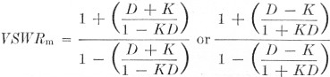
It is easily seen that the measured value, Km, of the reflection coefficient can vary appreciably because of D and the phase of the incident and reflected voltages. The v.s.w.r. as derived from the measured reflection coefficient is
![]()
and thus can vary between the extremes(1)
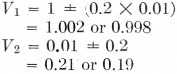
For example, if a line has a true v.s.w.r. of 1.5 to 1, the actual magnitude of the voltage reflection coefficient is
![]()
which, incidentally, represents 4 per cent reflected power. Now if the directional coupler used to measure it is a poor one - directivity equal to, say, 10 dB - it will discriminate by a factor of 0.316 between the backward and forward waves, and it can be demonstrated that it is indeed inaccurate as a v.s.w.r. measuring device:
Forward coupler:
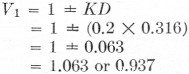
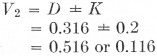
Backward coupler:
![]()
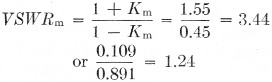
as possible values of indicated v.s.w.r.
On the other hand, a very good coupler with a directivity of 40 dB (0.01 discrimination factor between voltage waves of opposite directions) would more accurately determine v.s.w.r. under the same conditions:
(The fact that one of these numbers should be negative can be ignored, since the r.f. phase has no significance after rectification in the voltmeter circuit.) Then
![]()
and
![]()
It is not intended here to discuss techniques involved in designing directive couplers of high directivities or the method by which one may measure the directivity of a coupler. However, should an attempt to determine directivity be made, it is absolutely necessary that it be done with a line as nearly flat as possible. It is an extremely difficult measurement to make with any degree of accuracy since a line with a v.s.w.r. as low as 1.012 would give a measured directivity somewhere between 36.5 and 46.0 dB, when the actual directivity is 40 dB.
One should be cautious in quoting v.s.w.r. figures obtained by use of a device of this nature unless all its characteristics are known. Fig. 1 is a graph showing possible extreme indicated values vs. actual v.s.w.r. for couplers of various directivities.
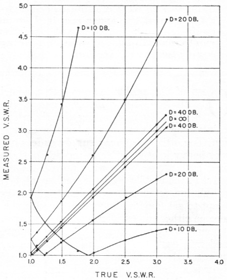
Fig. 1. Extreme values of indicated v.s.w.r. vs. actual v.s.w.r. for directional couplers having various directivity factors.
To determine whether a coupler has a high enough directivity to be dependable, one perhaps could insert it at various places in the line over a quarter-wave distance and see if the indicated v.s.w.r. changes appreciably.
Notes
- The sign of the reflection coefficient will, of course, be the same for both the forward and backward measurements, in a given. case. However, in the absence of a known reason for the finite directivity factor of the coupler it is safest to assume, in estimating the extreme limits of error, that the phase of the error voltage introduced by D can reverse when the coupler is reversed in the line. In these equations, this is equivalent to assuming that D can be either positive or negative. - Editor.
Louis D. Breetz, W3KDZ/W8QLP.