Grounded screen-grid operation for tetrodes
Limiting control-grid dissipation.
A tetrode with control grid and screen tied together to form a high-μ triode for a grounded-grid circuit makes a very simple arrangement. However, this type of operation invariably results in excessive control-grid dissipation. This article shows a simple method of avoiding this difficulty.
Grounded-grid operation is attaining more and more popularity, and is especially attractive when tubes are used which permit dispensing with bias and screen supplies. Other advantages may be listed, in addition to this simplification of circuitry. In particular, no loading of the exciter with noninductive resistors is required, and a large percentage of the driving power appears in the output of the final.
Control-grid dissipation
Listening around the ham bands, one comes to the conclusion that tubes readily available do not quite fit the application, if a kilowatt input is desired. 304THs are quite popular, but require fixed bias to hold the resting plate current down to a safe value. Most tetrodes require no bias if the screen and grid are tied together for a high-μ triode connection. The static plate current is then within safe limits, but the combined screen and grid current, under operating conditions, is objectionably high, approaching the plate current in magnitude. This not only presents an undesirable load to the exciter, but may result in exceeding the rated grid dissipation. The control grid draws the lion's share of the combined grid and screen current, but is least able to handle the dissipation. Screen grids are commonly rated at from two to four times the dissipation of the control grid. What is needed is a device to force the screen to carry its fair share of the load.
Reducing control-grid current
If the screen were to receive more excitation than the grid, our difficulties would be solved. Recent articles appearing in amateur publications have described the construction of bifilar filament chokes wound with enameled wire on 1-inch-diameter forms of materials such as micarta, bakelite, or dry broomstick. It is simplicity itself to tap down on these chokes a suitable distance for the grid connection, as shown in the circuit diagram of Fig. 1, instead of grounding the grid directly. This provides a voltage divider approximately equal to the turns ratio.
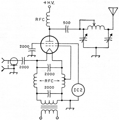
Fig. 1. Circuit of the grounded-screen amplifier with the control grid returned to a tap on the bifilar filament choke.
The screen-to-grid amplification factor of most tetrodes, such as the 4-65A, 4-400A, and similar tubes, is approximately 5. With the screen and grid driving voltages proportioned in this ratio, it was reasoned that the grid and screen currents would be at least somewhere near equal. This proportion is obtained, of course, by tapping down from the filament end of the bifilar choke of the total winding length.
In order to obtain some idea of operating conditions to be expected, a 4-400A was set up under static conditions, and a comparison made between the 5-to-1 ratio of screen-to-grid voltage, and with the grids tied directly together. These tests revealed that, with a plate voltage of 500 (approximating the epmin to be expected), and with the grids tied together, a plate current of 140 mA was obtained with a grid/screen voltage of 30. The combined grid current was 100 mA!
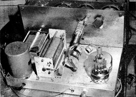
Typical layout for a grounded-screen amplifier with pi-network output. The input capacitor is of the vacuum-variable type. In this instance, the meters are shielded by a subpanel. The tube is a 4-400A. Most of the components are surplus items.
With the 5:1 ratio, the same plate current of 140 mA was obtained with the screen at 75 volts and the grid at 15 volts. The respective grid currents were 10 ma. for the screen and 18 mA for the grid, or a combined current of only 28 mA - only 28 per cent as high as for the direct connection. Of course, the screen voltage was now 2½ times as high as the previous value of 30, but this does not mean that 2½ times as much drive is required.
There is considerable degeneration involved in grounded-grid operation, and with the grid tapped down on the filament choke 3i of the distance from filament to ground, it sees only about 3; of the degeneration or inverse-feedback voltage. The actual additional excitation required will be from 25 to 40 per cent of that required for the triode connection. However, since the total grid dissipation is reduced, a much larger percentage of the power from the driver reappears in the output.
The ratio of 5:1 is not necessarily an optimum value. The grid current was found to exceed the screen current only at low drive. Under normal operating conditions, the screen current was found to be about twice the grid current. A lower turns ratio might therefore be acceptable, requiring less drive but still not exceeding the grid dissipation.
Practical operating conditions
Now for practical cases. An extrapolation of the curves obtained from the static tests on the 4-400A gave some indication of the amount of grid and screen driving voltages that would be required for 1-kw. input. Fortunately, there is no need to guess about these matters. Eimac maintains an Amateur Service Department, and an Application Department, and upon request to them, the plate curves will be supplied.(1)
Since this type of operation approximates Class B, the operating conditions may be calculated accordingly. Assuming that an input of 1 kW with a plate voltage of 3000 is desired, the plate current will be 325 mA (to be on the safe side). The peak current, ipmax, will then be π times the average current, or pretty close to 1 ampere. Power output (Po) is calculated from
![]()
This represents an efficiency of 64 per cent and a safe plate dissipation of 375 watt under conditions of sustained, or c.w. drive. In addition, a large percentage of the power delivered by the exciter appears in the output, and is roughly equal to the exciter Po minus screen and grid dissipation.
Grid and screen dissipation
Both screen and grid dissipation can be calculated approximately from:
![]()
For the screen, this equals ![]() or 32 watts, with 3.5 watts grid dissipation. These figures are all well within the maximum ratings for this tube, the latter being 35 watts and 10 watts for the screen and grid, respectively. Thus, such an amplifier is suitable for c.w. or a.m., as well as s.s.b. where the low average characteristic of speech waveforms is normally relied on to avoid exceeding grid dissipation. In fact, the operating conditions are almost identical with those for normal Class C operation.
or 32 watts, with 3.5 watts grid dissipation. These figures are all well within the maximum ratings for this tube, the latter being 35 watts and 10 watts for the screen and grid, respectively. Thus, such an amplifier is suitable for c.w. or a.m., as well as s.s.b. where the low average characteristic of speech waveforms is normally relied on to avoid exceeding grid dissipation. In fact, the operating conditions are almost identical with those for normal Class C operation.
Average screen and grid currents were calculated by dividing the peak currents by a. This brings us to a consideration of drive requirements. Since the grid dissipation is a small part of the total, we will not be far off by considering the 4-400A as a triode, with the screen as the control grid. This allows us to use the usual formula for total power required from the driver, in grounded-grid operation:
![]()
Taking Ipm (peak fundamental plate current) as ½ ipmax or 0.5 ampere, this becomes
![]()
The combined screen and grid dissipation is 35 watt, so 77 watt of the exciter power will be delivered to the antenna, neglecting circuit losses.
Now for a comparison of calculated and actual operating conditions. A 4-400A was easily driven to an input of 1 kW with slightly more than 100 watt from the exciter. Judging by the color of the plate, the plate dissipation was well under 400 watts. The screen and grid currents were 62 mA and 24 mA, respectively, for a sustained input of one kilowatt. Good results were obtained in c.w., a.m. and s.s.b. on 80 and 40 meter.
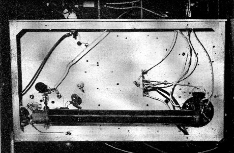
Bottom view of the grounded-screen amplifier showing the mounting of the tapped bifilar filament choke.
However, when attempts were made to drive the amplifier on 20 meter, it was found that the bifilar choke in use was too large to permit full input. Also, the impedance with such a large choke presented an undesirable load to the exciter. It is probable that proper loading of some of the popular exciters built from kits, where the output is usually tuned with a pi network designed to work into a resistive load of not over 600 ohm, would be found impossible.
Further experimenting showed that a smaller choke would permit full input on 20 meters as well as on the two lower-frequency bands. This choke consisted of two strands of No. 14 enameled wire close-wound simultaneously on a 1 inch diameter form to a winding length of 6 inch. The grid tap was placed at 1½ inch from the filament end of one of the two windings, the transformer end of the same winding being grounded, as in Fig. 1. The voltage drop across this choke, using a 4-400A tube, is 1.3 volt which is just right for operating the 5 volt filament from a 6.3 volt filament transformer. Experimentation with an even smaller choke should make possible operation on 20, 15 and 10 meter, but it is doubtful that a single choke could be designed that would work satisfactorily on all five bands.
Other tubes
This takes care of the 4-400A, a popular tube capable of handling a kilowatt input with ease. How about other tubes? An interesting article recently appeared in one of the amateur publications, describing the use of four 4-65As in parallel, in grounded grid, with the screen and grid tied together. K7BYQ had constructed such an amplifier. It performed very well, but the grid current meter was sometimes pinned at 250 mA! It-took only a few minutes to install the grid tap on the bifilar choke, after which the grid current was reduced to 20 mA, with 50 mA for the screen current - this for the same input in both cases of 400 mA at 2000 plate volt. The same rig was used for a quick check on the 4-400A calculations.
The accompanying photographs show the amplifier used for the experimental tests. The bottom view shows the original filament choke with the grid tap at about one-fifth the total number of turns from the top. The bypassed resistor connected at this tap was used for metering purposes. A grid-current meter would have to be mounted on stand-off insulators to reduce its capacitance to ground, since the grid is not at ground potential. In regular operation a grid meter is not necessary, a screen-current meter alone being adequate. If the tube socket is positioned as shown, with the two filament terminals toward the top, short leads will result. Don't forget the bypass directly from screen terminal to ground.
Notes
- Eimac advises that there is a possibility that similar curves for other tetrodes will be available in the near future; also constant-current curves.
V.S. Campbell, K7BYQ
W.S. SKEEN, W7EPM.