A complete break-in unit for c.w.
Combining keying wave shaping, antenna t.r. switching, receiver muting, and side tone.
This unit does everything you need for effective c.w. break-in operation, including amplitude limiting of incoming signals and elimination of keying and switching clicks in the receiver. It's based on using a "silent" v.f.o., the alternative to oscillator keying.
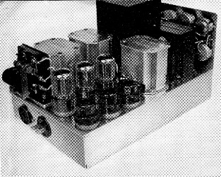
The break-in unit built by W2LYH makes liberal use of surplus and salvaged ("junk box") components, but suitable currently catalogued items readily can be substituted. The chassis size is 7 × 11 × 2 inches. The circuit layout is not critical, and may be varied to suit the builder's taste. The panel at the far end has the nine potentiometer controls and the phone jack mounted on it.
One of my favorite ham radio subjects has always been break-in c.w. operation, and the different methods of obtaining it. Since descriptions of these methods have been very interesting to me, I thought that perhaps the system used at this station might be of some interest to others who have been working on the same problem. The system provides full break-in operation, in which the breaking signal can be heard between dots at the fastest sending speed, with no compromise in the quality of the transmitted signal. It uses only one antenna and gives monitoring of the keying without clicks or thumps in the headphones. Most of the functions of the system have been combined into one unit, as shown in the photographs. These functions will be described separately.
Transmitter keying
The transmitter uses a shielded v.f.o. unit with a continuously-running oscillator and two untuned Class A buffer stages, and grid-block keying is applied in a stage which doubles to 80 meters. The local signal is absolutely inaudible on any band with the key up, so there is no need to key the oscillator,(1) and the keying can be shaped as desired by adjusting the constants of the keyer circuit.
The blocking bias is supplied by a half-wave rectifier, V6B, Fig. 1. The leading and trailing edges of the keying envelope are adjusted by means of R9 and R10. The purpose of diodes V6A and V6B is to separate these two adjustments, so that one does not affect the other. When the key is closed, capacitor C1 discharges through V6B and R9, thus shaping the leading edge. When the key is opened, capacitor C1 charges through V6A and L1, thus shaping the trailing edge.
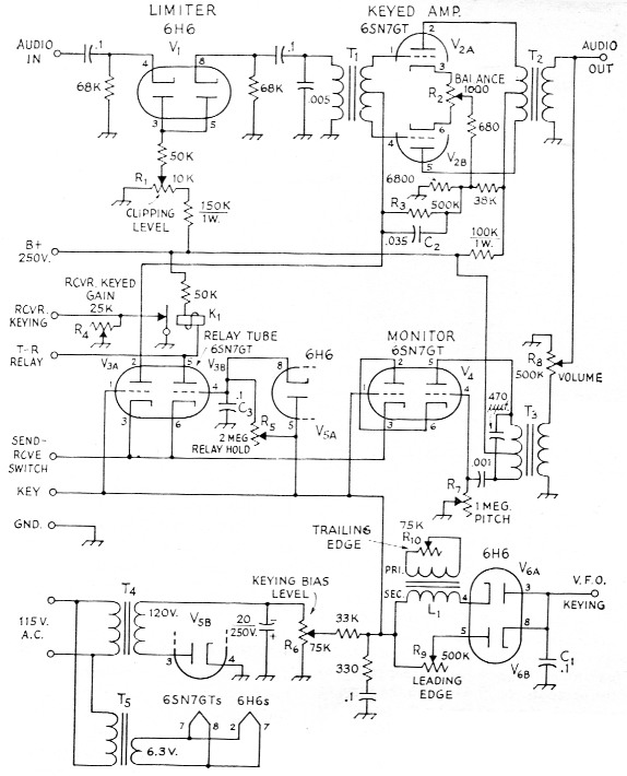
Fig. 1. Circuit diagram of the c.w. break-in unit. Return paths for keying, audio and send-receive switch circuits are to ground (chassis). See Fig. 3 for t.r. relay circuit. Unless otherwise indicated, capacitances are in µF, resistances are in ohms, fixed resistors are ½ watt. Capacitors with polarity marked are electrolytic; others may be paper, mica, or ceramic as convenient.
| C1,C3 | 0.1 µF paper. |
| C2 | 0.035 µF paper. |
| K1 | Fast-acting sensitive relay, s.p.s.t. or s.p.d.t. (see Fig. 3). |
| L1 | Audio transformer, interstage type; see text. |
| R1,R2 | Composition control, linear taper. |
| R3 | 500 kΩ, ½ watt. |
| R4,R6 | Composition control, linear taper. |
| R5,R7,R8 | Composition control, audio taper. |
| R9,R10 | Composition control, linear taper. |
| T1 | Interstage audio transformer, single plate to p.p. grids (any type satisfactory). |
| T2,T3 | Output transformer, plate to line type (Thordarson 22S72 or equivalent suggested). |
| T4 | Power transformer, 125 volt at 15 mA. (Stancor PS-8415 or similar). |
| T5 | Filament transformer, 6.3 volt at 3 A. |
Inductance L1 could be replaced with a resistance but, as pointed out by W1DX,(2) while an RC circuit gives a good leading edge shape, a better trailing edge shape is obtained with an LC circuit. This is shown in Fig. 2. It is possible to round off the trailing edge nicely without putting tails on the signal, and the envelope as seen on a scope shows the same shape on the leading and trailing edges. In a high-impedance keying circuit such as this, a rather high inductance value is required for Li. - something on the order of 500 to 1000 henrys. The secondary winding of a junk-box audio transformer has worked very well, and a good range of adjustment is obtainable by shunting the primary winding with R10.
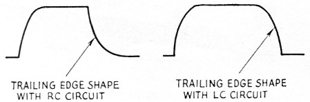
Fig. 2. Trailing-edge wave shapes with RC and LC circuits.
The shape of the keying envelope seems to be unaffected by the following stages of the transmitter if no stage is overdriven. Naturally, if a stage is driven beyond the point where its output ceases to rise it will act as a limiter and will tend to square up the keying envelope. The v.f.o. is provided with an output control, which is set at the point where the antenna current just starts to drop. This control is also used for adjusting the power output of the transmitter, giving smooth control from zero to maximum.
Limiter and keyed audio stage
The audio output of the receiver is fed through a limiter, Vt, and a keyed audio amplifier, V2, to the headphones. The limiter prevents signals from rising above a chosen audio level, and is quite useful for saving the eardrums. The keyed amplifier serves to disconnect the phones from the receiver when the key is down, so that any clicks or thumps which might be generated in the receiver are not heard. When the key is closed, V3A conducts, and the voltage drop across R3 and C2 instantly biases both triodes of V2 beyond cutoff. When the key is opened, the triodes do not conduct again until 02 has discharged through R3, giving a few milliseconds delay, during which time the transmitter output drops to zero, the receiver r.f. gain is keyed to normal level, and the antenna is switched to the receiver. A push-pull amplifier is used so that the plate current can be cut off sharply without causing a click in the phones. Potentiometer R2 is set to the point where the click is balanced out.
Relay tube
The "relay tube", V3, performs two functions. One triode keys the audio amplifier, V2, as just described. The other has two relays in its plate circuit. One relay (Fig. 3) serves as a t.r. switch, and the other, K1, keys the receiver r.f. gain by the well-known method of lifting the normally-grounded end of the r.f. gain control from ground. Since there is no need to reduce the gain all the way to zero, R4 is included to provide a means for adjusting the key-down gain; this gives the relay contacts less work to do, and also permits monitoring the transmitted signal directly at the receiver output if desired. It is evident from the circuit diagram that when the key is closed, capacitor C3 will discharge rapidly through diode V5A, triode Via will conduct, and both relays will operate. The relays are closed before any r.f. comes from the transmitter.
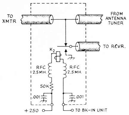
Fig. 3. Coax-line break-in relay circuit. In actual construction, a single chassis-mounting type coax connector is used atthe junction of the lines from the transmitter and antenna tuner, with a "Tee" fitting for making the connection, as shown in one of the photographs. The relay is the same as the keying relay in Fig. 1; the one used by the author is a Signal Corps type BK-35, but any fast-acting relay having a 10,000-ohm coil can be used. Suggested alternatives are the Sigma 4F, 5F or 11F, Advance SV, Potter & Brumfield SS5D, or Struthers-Dunn 1 AXA124.
While it is desired that the relays operate quickly when the key is closed, they should hold in for a few milliseconds after opening the key, until the transmitter output has dropped to zero. This action is achieved by allowing C5 to discharge rapidly through diode V5A when the key is closed, and to charge more slowly through R5 when the key is opened. The cathodes of the relay tube and the audio oscillator are returned to ground through one pair of contacts on an external d.p.s.t. "send-receive" switch, the other contacts of which control the transmitter power supplies. When the switch is in the receiving (open) position the break-in system is thus disabled, to allow spotting of the v.f.o. frequency.
T.r. relay
The t.r. relay performs the same function as the more commonly used tube-type t.r. switch. When the key is open the receiver input is connected to the coax cable inner conductor through the normally closed contacts of the relay, as shown in Fig. 3, and when the key is closed the receiver is grounded through the normally open contacts. Note that the relay does not handle any power, its only function being to lift the receiver off the coax line.
Since the r.f. voltage on the coax line is low, almost any type of small fast-acting relay is suitable. The one used here is the same type as the one which keys the receiver r.f. gain, shown in the photograph. The t.r. relay is mounted in a small metal box provided with coax fittings. A "tee" fitting is convenient for connecting it into the line. An antenna tuner is used for matching open-wire feeders to the coax line.
This relay t.r. switch has performed perfectly on all bands, 80 through 10 meters, and while I don't claim that it has any signal gain, it has no loss either. Also, it generates no spurious signals or TVI, and feeds much less r.f. into the receiver from the transmitter than any tube-type t.r. switch I have tried.
Keying monitor
A blocking-type audio oscillator is used as a keying monitor. One triode of V4 serves as a keyer for the oscillator, to isolate the v.f.o. keying circuit from any voltage that is developed at the grid of the oscillator due to the blocking action. This oscillator gives a very distorted wave, which is desirable for monitoring. A sine-wave audio oscillator was used at one time, but it was very tiring to the ears. R7 adjusts the pitch of the tone, and R8 adjusts the level.
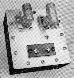
The t.r. switch, a keyed relay of the same type used in the break-in unit, is mounted in a 4 × 4 × 2 inch metal box. Practically any fast-acting sensitive relay can be used since the contacts do not have to carry r.f. current.
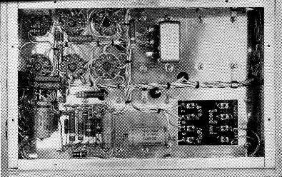
A neat wiring and cabling job makes the bottom of the chassis look simple. The power transformer visible through the cutout at the lower right is a surplus item combining the plate and filament functions specified in Fig. 1 for T4 and T5
Analysis of operation
The sequence of the over-all operation is shown in Fig. 4. Potentiometer R6 in the grid-blocking supply is provided for setting the level of the blocking bias. To key the v.f.o., it is required only that this voltage be set to a value sufficient to cut off the keyed stage. However, if we set the voltage slightly beyond this point, there will be a time interval, with proper shaping of the leading edge, after the key is closed and before there is any output from the v.f.o., which can be used for setting the system to the transmitting condition. During this period the phones are disconnected from the receiver, the receiver r.f. gain is reduced, and the antenna is switched, all before any r.f. comes from the transmitter. When the key is opened, the transmitter output falls to zero, the relays open, and the keyed audio amplifier again connects the phones to the receiver.
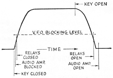
Fig. 4. Sequence of events in the operation of the break-in unit on each dot or dash. V.f.o. output is cut off during the time the keying voltage is below the dashed line.
This action is repeated for every dot and dash, giving the maximum opportunity to hear a breaking signal without the annoyance of clicks and thumps in the phones.
Adjustment
The nine potentiometers mounted on the panel provide the adjustments required for setting up the system for smooth operation. The first step is to set the keying bias level (R6) somewhat beyond the voltage required to block the keyed stage. Then the leading and trailing edges are shaped (R9 and R10) to give the desired keying characteristics. Next, the "relay hold" control (R5) is set so that the relays hold in until the transmitter output has dropped to zero, as determined by listening directly at the receiver output. If the relays open too soon, a loud click will be heard when the key is opened. R5 should be set just beyond the point where this click disappears. The "amplifier balance" control (R2) should be adjusted to balance out any click which might be heard at the instant of closing the key. The limiter control (R1) sets a maximum on the level of audio signal in the phones, and should be set so that no clipping occurs on normal signals. The pitch (R7) and volume (R8) of the keying monitor can be adjusted to suit your preference, and then you are all set for some smooth break-in c.w. operating.
The only way I can think of to improve on the system would be to locate the transmitter about ten miles away, but it's handier to have it within reach.
Notes
- This requires using a low-frequency (160 meter or broadcast band) v.f.o. followed by a Class A amplifier, both well-shielded, before the keyed stage. Such a unit was described in QST for February, 1950 (Smith, "A solution to the keyed V.F.O. problem").
- Goodman, "Chirp-free break-in keying," QST, October, 1953.
Robert V. McGraw, W2LYH.