A table-top half kilowatt
Grounded-grid parallel 811As for s.s.b. or c.w.
An amplifier-cum-power supply on one chassis is a convenient package to have, especially when it fits in a receiver-size table-type cabinet and can be run at a half kilowatt input. Add constructional simplicity, a minimum of operating controls, and pleasing appearance and you have the article described here.
The amplifier shown here will run at about 500 watts input on c.w. - or p.e.p. input as an s.s.b. linear - on all bands from 80 through 10 meters. I wanted a simple amplifier that would be small and neat, and with which I could change bands quickly. The result is small enough to sit on the operating table right along with the rest of the station equipment; no need for big racks here!
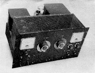
This amplifier operates at a plate input of approximately 500 watts, uses a pair of 811As in grounded-grid, and is complete with power supply on a 13 × 17 × 4 inch chassis. The rack panel is 10½ by 19 inch. Front-panel controls, arranged to give a balanced appearance, include the plate tuning capacitor and band switch in the center, filament and plate power switches with their pilot lights at the lower left, sensitivity control and forward-reflected power switch for the directional coupler at the lower right, variable loading capacitor and auxiliary loading-capacitor switch underneath the 0-1 milliammeter at the right, and the grid-cathode milliammeter with its switch at the upper left. The filter choke, 866As and plate transformer occupy the rear section of the chassis.
Using a pair of 811As in parallel in the grounded-grid circuit, this rig is a good one to use following transmitters such as the Viking Ranger, DX-40, Globe Scout, and others of similar power class, for a worth-while increase in power output on c.w. As a linear amplifier following an s.s.b. exciter it requires no swamping not only because the 811A grids provide a fairly constant load in themselves, but also because the fed-through power with grounded-grid presents an additional constant load to the driver. The total driving power needed on any band is less than 20 watts.
An additional useful feature is a built-in directional coupler using a version of the "Mickey Match." 1 Besides its obvious application for checking the s.w.r. on the transmission line to the antenna or for help in tuning up a coax-coupled antenna coupler, it is practically indispensable as an indicator of relative power output in tuning the amplifier, for reasons which will be discussed later.
The Circuit
A number of tube types could be used in an amplifier of this power class, but I decided on the 811As because they do not need a bias supply and are not expensive. (Surplus 811s can be used if you don't want to buy new tubes; the ratings are not quite as high but they can be pushed a bit in intermittent service such as c.w. and s.s.b.)
The complete circuit is shown in Fig. 1. Don't expect to find anything startling - the whole thing was taken from parts of proven circuits here and there in the Handbook and put together to meet my needs. To save trouble and work, standard components were used throughout - the only special construction is the shielding and a few simple r.f. chokes. The tube filaments are driven directly from coax input from the driver; no tuning is used or is needed in this circuit. The filaments are kept above ground by the B & W type FC15 filament choke.
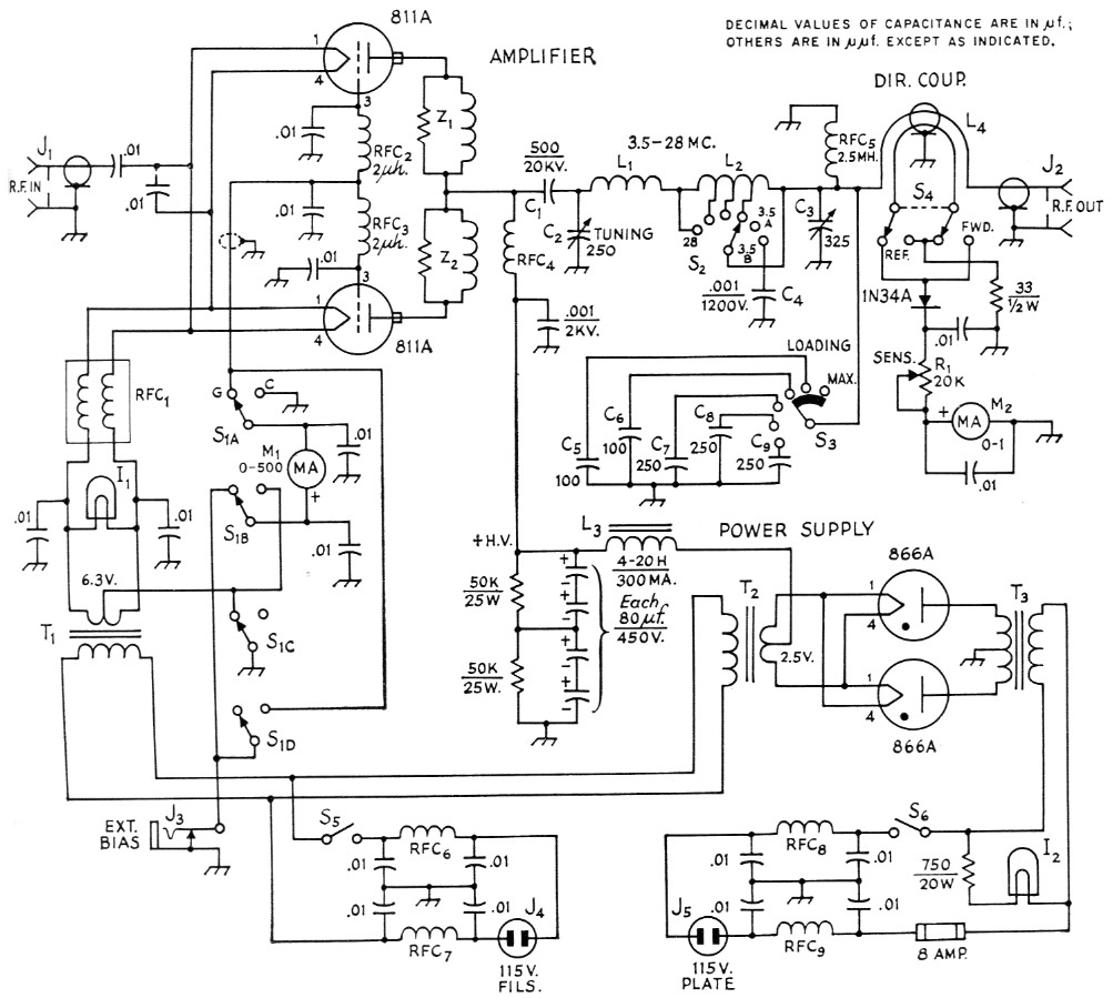
Fig. 1. Circuit diagram of the parallel-811A grounded-grid amplifier. Unless otherwise specified, fixed capacitors are disk ceramic, 600-volt rating.
| C1 | 500 pF, 20,000 volts (TV "doorknob" type). |
| C2 | 250 pF variable, 2000 volts (Johnson 250E20). |
| C3 | 325 pF variable, receiving type (Hammarlund MC-325-M). |
| C4-C9 inc | 1200 V mica, case style CM-45. |
| I1,I2 | 6.3 volt dial lamp, 150 mA (No. 47). |
| J1,J2 | Coax connector, chassis mounting. |
| J3 | Closed-circuit phone jack. |
| J4 J5 | 115 V male connector, chassis mounting (Amphenol 61-M1). |
| L1,L2,S2 | 5-band pi-network coil-switch assembly; see text (B & W 851). |
| L3 | Swinging choke, 4-20 H, 300 mA (UTC S-34). |
| L4 | Section of coax line with extra conductor inserted; see Footnote 1 for construction references. |
| M1,M2 | Milliammeter, 3½ inch plastic case (Triplett 327-PL). |
| R1 | 20 kΩ composition control, linear taper. |
| RFC1 | Filament-choke assembly, to carry 8 amp. (B & W FC15). |
| RFC2,RFC3 | 2 µH (National R-60). |
| RFC4 | 90 µH; 4_3/8 inch winding of No. 26, 40 t.p.i., on ¾ inch ceramic form (B & W 800). |
| RFC5 | 2.5 mH, any type. |
| RFC6-RFC8, incl. | 18 turns No 14 enam., close-wound, ½ inch diam., self-supporting. |
| S1 | 4 pole 2 position rotary, nonshorting (Mallory 3242J or Centralab 1450). |
| S2 | Part of tank assembly; see L1L2. |
| S3 | Miniature ceramic rotary, 1 section, 1 pole, 6 positions used, progressive shorting (Centralab 2042). |
| S4 | Miniature ceramic rotary, 1 section, 2 poles, 2 positions used, nonshorting (Centralab 2003). |
| S5,S6 | S.p.s.t. toggle. |
| T1 | Filament transformer, 6.3 volt, 8 amp. min. (UTC S-61). |
| T2 | Filament transformer, 2.5 volt, 10 amp. (UTC S-57). |
| T3 | Plate transformer, 3000 volt center-tapped, 300 mA d.c. (UTC S-47). |
| Z1,Z2 | Parasitic suppressor, 100 ohm 2 watt carbon resistor assembled inside 2½ turn coil of No. 16 tinned, ½ inch diameter, 3¾ inch long. |
The plate tank is the familiar pi network, using a B & W type 851 tapped coil and band-switch assembly. This assembly has been modified slightly in two respects: First, the copper-strip 10 meter coil normally mounted at the top of the rear plate was taken off and moved so that it is supported between the tank assembly and the stator of the tank tuning capacitor as shown in the top view. A short length of copper strip is bolted between the free end of the coil and the right-hand stator connection of the tuning capacitor, to support the free end. This change was made in order to avoid the long lead that would have had to be run from the capacitor to the regular input terminal on the tank assembly, ksinee this terminal is at the right-hand side of the assembly as viewed from the top. The turns of the 10 meter coil were also squeezed together a bit to increase the inductance, because it was found that a rather large amount of capacitance had to be used to tune the circuit to the band with the coil at its original length. The length is now 1_5/8 inch between mounting holes.
The second modification was the addition of a pair of switch contacts on the rear switch plate of the tank assembly. There is an extra position on this plate with holes already provided for contacts, and it seemed like a good idea to use a set of contacts here to switch in additional output loading capacitance on 80 meters, where a large output capacitance is needed. The variable loading capacitor, C3, and the five fixed mica capacitors, C5 to C9 inclusive, give continuous variation of capacitance up to 1275 pF on all bands, including the regular band-switch position for the 80 meter band. However, if the switch is turned to the extra position an additional 1000 pF mica capacitor is connected in parallel, so that continuous variation of capacitance to over 2200 pF is possible on 80. This takes care of cases where the load resistance happens to be unusually low or reactive.(2)
A 500 mA d.c. meter is used for reading either total cathode current or grid current alone. The cathode current is read in preference to plate current because of safety considerations. Putting the meter in the hot d.c. plate lead leaves nothing but a little plastic insulation between the high voltage and the meter adjusting screw. Although the meter could have been connected in the negative plate supply lead since the power supply is self-contained, I prefer to have the negative firmly grounded to the chassis. It is a bit of a nuisance to have to subtract the grid current from the cathode current in order to find the plate current, but it isn't serious. The d.c. grid circuit has a jack, J3, for introducing external bias either for blocked-grid keying or for cutting off the plate current during receiving, and a four-pole switch, Si, is therefore needed for handling the meter switching while keeping all circuits functioning normally.
The power supply uses 866As with a plate transformer giving 1500 volt each side of the center tap, and working into a single-section choke-input filter. The filter capacitor consists of four 80 µF electrolytics connected in series to handle the voltage, giving an effective filter capacitance of 20 µF. This supply is running well below its capabilities in the intermittent type of operation represented by c.w. and s.s.b., and the amplifier is somewhat "over-powered" in this respect. A lighter plate transformer can be used since the average current in regular operation is only about half the maximum tube rating of 350 mA for the pair. However, a heavier supply was used here because plate modulation may be tried some day. This might make it necessary to use a tank capacitor with larger plate spacing (3000-volt rating instead of 2000 volt, which is plenty adequate for c.w. and s.s.b.) but there is room enough to install a capacitor about two inches longer if it is needed.
The a.c. inputs to both filaments and plates have TVI filters installed right at the a.c. connectors. The chokes in these filters, RFC6 to RFC6 inclusive, are homemade by winding 18 turns of No. 14 enameled wire close-wound on a half-inch dowel or drill.
Construction
The ordinary principles of good construction as given in the handbooks were followed in layout and assembly. The only space available for the filament transformers was below chassis, so these were mounted on the front wall of the chassis as shown in the bottom view. There is plenty of room for all other power-supply parts below chassis, and the photographs make any further comment on this section unnecessary.
The r.f. layout shown in the top view is almost an exact copy of the circuit layout as given in Fig. 1. The plate blocking capacitor, C1, is mounted on a small right-angle bracket fastened to the left-hand stator connection of the tank capacitor, C2. The tube plates are connected to C1 through individual parasitic-suppressor assemblies, Z1 and Z2. The hot end of the plate choke, RFC4, also connects to this same point. The tank capacitor is mounted on h-inch ceramic pillars to bring its shaft to the same height as the switch shaft on the tank-coil assembly. The capacitor is grounded by connecting the bottom of its frame through a half-inch wide strip of aluminum to essentially the same point at which the plate-choke bypass capacitor, a 1 nF 2000 volt disk, is grounded. The ground end of the aluminum strip actually is under the bottom of the plate choke, and the ground lug for the bypass capacitor is just to the left. This strip, plus short leads in the circuit from the tube plates through the tank capacitor to ground, keeps the resonant frequency of the loop thus formed well up in the v.h.f. region; this is important because it permits using low-inductance parasitic chokes in shunt with the suppressor resistors, and thus tends to keep the r.f. plate current at the regular operating frequencies out of the resistors. With other tank grounding arrangements originally tried, larger parasitic chokes had to be used and it was impossible to prevent the resistors from burning up when operating on 10, 15 and even 20 meter. Now they do not overheat on any frequency, and v.h.f. parasitics are nonexistent - although without the suppressors the parasitics are only too much in evidence.
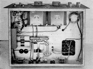
In this below-chassis view, the two filament transformers are at the top, mounted on the chassis wall. The 81 1 A sockets are at the upper left. The rectangular box on the left-hand wall contains the FC15 filament-choke assembly. The "Mickey Match" directional coupler is at the upper right. Filter capacitors and the bleeder resistors are in the lower section. A.c. inlets, fuse holder, bias jack, and the 115-volt line TVI filters are on the bottom chassis wall.
The output loading capacitors, C3 through C9, are mounted toward the rear so the leads from the tank coil can be kept as short as possible. A length of copper strip is used between the coil and the stator of C3; originally this lead was No. 14 wire but on 10 meters the tank current was enough to heat it to the point of discoloration. The ground lead from the fixed units, made to the rear bearing connection of C3, is also copper strip. C3 and 23 are operated through extension shafts, using Millen flexible couplings to simplify the alignment problem.
Underneath the chassis, each 811A grid is bypassed directly to the socket-mounting screw nearest the plate choke (right-hand side of the socket in the bottom view). The d.c. leads have small chokes, RFC2 and RFC3, with additional bypasses for good r.f. filtering, particularly at v.h.f. since grid rectification generates harmonics in the TV bands. The filament choke, RFC1, is mounted so that the filament side is close to the filament terminals on the tube sockets; the other end is bypassed directly to the chassis.
The shielding around the amplifier consists of two pieces of sheet aluminum and a perforated aluminum ("do-it-yourself " type) cover having the shape of an inverted U. The top view shows how the rear wall is made. Its edges are bent to provide flanges for fastening the cover with sheet-metal screws, and there is a similar flange projecting to the rear at the bottom for fastening the wall to the chassis. The front piece extends the full height of the panel and is identically drilled and cut out for meters and controls. It has flanges at the top and extending down the sides from the top to the chassis. The cover itself extends down over the sides of the chassis for about one inch. Numerous screws are used for fastening the cover, to prevent leakage of harmonics.
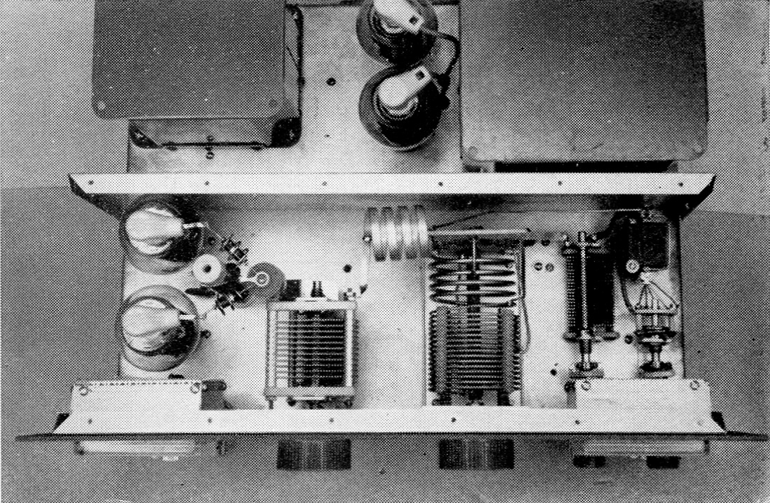
The r.f. section with the shield cover removed. Components here are readily identifiable by reference to the circuit diagram. The meters are enclosed in rectangular boxes made from thin aluminum sheet, formed to be fastened by the meter mounting screws. The back covers on these boxes are made from perforated aluminum, folded over at the edges and held on the boxes by sheet-metal screws. The switch for shifting the 0-500 milliammeter (left) from grid to cathode is concealed by the box which encloses the meter.
The shields over the meters are made as described in the caption for the inside top view. Meter leads are bypassed to the shield boxes where they emerge.
The Handbook should be consulted for methods of checking and adjustment of the directional coupler.
Operating conditions and tuning
The voltage delivered by the power supply is approximately 1500 volts with no drive and with the tubes taking only the no-bias static plate current, which is about 60 ma. At the full load of 350 ma. the voltage is slightly under 1400. Optimum operating conditions for 1400 volts at 350 ma. peak-envelope power input as an s.s.b. linear call for a peak-envelope grid current of 60 ma. The peak-envelope tube power output is close to 350 watts under these conditions. The same Operating conditions are also about optimum for c.w.
The behavior of the cathode current when tuning a grounded-grid triode amplifier is extremely confusing, and the meter is principally useful as a check on operating conditions rather than as a tuning indicator. The best indicator of proper timing of the plate tank capacitor is the forward-power reading of the directional coupler. For any trial setting of the loading controls and driving power, always set the plate tank capacitor control at the point which results in a maximum reading on the power-output indicator. The power indications are only relative, of course, and the sensitivity control should be set to give a reading in the upper half of the scale.
The objective in adjusting loading and drive is to arrive at maximum power output simultaneously with a plate current of 350 mA and a grid current of 60 mA - that is, a total cathode current of 410 ma. when the grid current reading is 60 mA. The loading is critical. If the amplifier is not loaded heavily enough the grid current will be too high and the right value of total cathode current either will not be reached or, if reached, the amplifier will be operating in the "flattening" region as an s.s.b. linear. (It can be operated this way on c.w., however, since linearity is unimportant here.) If the loading is too heavy, the grid current will be low when the cathode current reaches the proper value, but the efficiency will be low and the tubes will overheat.
Getting the knack of it takes a little practice, but when the job is done right the tubes will run cool on all bands in regular operation. Running key-down over a period of time may show just a trace of dark red color on the plates since the input and dissipation are somewhat over ratings under these operating conditions, although perfectly satisfactory with ordinary keying or s.s.b. voice.
That's about it. Once you get it built and learn to operate it, you're in the high-power class - with a table-top job that takes up no more room than a good communications receiver. Nothing under the table, either.
Notes
- Bunce, "The 'Mickey match'," QST, November, 1958. A modified version also is described in the chapter on measurements in the 1959 edition of The Radio Amateur's Handbook. The circuit used here combines the r.f. switching of the original "Mickey Match" with the fixed load resistor used in the Handbook arrangement. - Editor.
- These contacts can be obtained directly from the manufacturer of the tank assembly. To secure a set of contacts with mounting hardware, send one dollar to Barker & Williamson, Beaver Dam and Canal, Bristol, Penna., specifying the type of tank assembly for which they are wanted. The contacts are not catalog items and are not available through dealers.-Editor.
Ernest A. Coons, W1JLN/FOE.