Radioteletype conversion from receiver i.f.
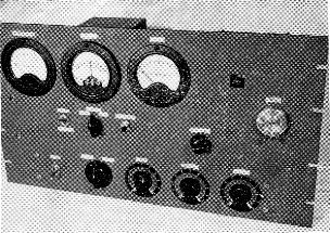
This teletype converter works from the i.f. output of any receiver having an intermediate frequency in the 190550-kc. region. Components on the 10½ × 19 inch rack panel include meters for reading plate current of the keyer stage, discriminator balance, and keying loop current. The controls immediately under the meters are the toggle switch to change from receiving to local keying, a calibrate switch, and push button for scope checking. Along the bottom of the panel are the power switch, signal reversing switch, and controls for per cent mark, sensitivity threshold, and r.f. gain of the BC-453 receiver incorporated in the unit. The BC-453 tuning control, "align input" knob, and window for reading the dial are in the right-hand section.
Surplus receiver combined with f.s.k. detection shaping and keying.
The i.f. type converter for radioteletype makes direct use of the f.s.k. signal, with suitable cleaning up and amplification, and does not require the sharp audio filters used in the two-tone method. Although at first glance the unit described here may seem to be elaborate, this is partly because it includes power supplies and a scope amplifier for adjustment and monitoring. The principal sections are shown in four separate diagrams; in only one, the converter proper, are there any techniques unfamiliar to the amateur without previous RTTY experience.
There are two general methods of receiving radioteletype. One is to use a discriminator to detect the signal shift at the intermediate frequency of the receiver. The other is the audio system, using two tones either received directly from a modulated signal or developed in the receiver by using the b.f.o. to beat against the shifting carrier, the audio tones then being separated in filters to develop the proper keying.
This article will discuss the circuitry and operation of an i.f. type converter or terminal unit that was constructed as a project for the Central Technical Net of the Air Force MARS program. Certain portions of the circuit were taken from the CV-57/URR military radioteletype converter, with various modifications to make the unit adaptable to currently-available surplus parts.
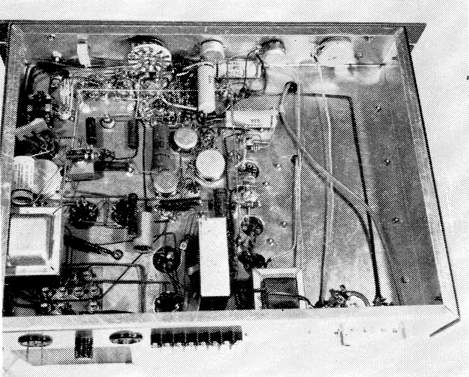
The loop-circuit relay, K2, is at the upper left in this view. Other principal components can be identified by their relationship to the top view, with the amplifier-trigger circuits at the upper left, power supply at lower left, and external i.f. strip running from rear to front just to right of center. Shielded leads through holes in the chassis under the BC-453 are used for r.f. and i.f. input and output connections.
Converter circuit
The CV-57/URR converter operates on receiver intermediate frequencies from 395 to 470 kc. The receiver's i.f. is converted to 40 kc., then amplified, clipped by a limiter and fed into a discriminator. The discriminator output is amplified, filtered, amplified again and then used to trigger two Eccles-Jordan flip-flop multivibrator stages in cascade to key the RTTY loop keyer tubes.
The main point of difference in the unit constructed here is the use of 85 kc., the intermediate frequency of the BC-453 Command receiver, as the second i.f. The 453 not only makes an excellent "front end" for the converter but is capable of tuning to any receiver intermediate frequency from 190 to 550 kc. The BC-453 is modified by removing the third i.f. can and the audio tubes, and then the plate of the 12SK7 second i.f. tube is coupled to an external i.f. strip using the same i.f. transformers as in the second stage of the BC-453 (part No. 7267). The signal next is passed through one stage of amplification and one stage of limiting, and then into a discriminator using two i.f. transformers as shown in Fig. 1.
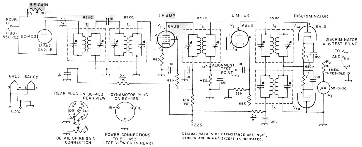
Fig. 1. Circuit of the 85 kc. i.f. amplifier-discriminator. Fixed resistors are ½ watt composition except as indicated. Except for the 1 µF capacitor, which is paper, and the 20 nF capacitors, which are disk ceramic, fixed capacitors may be either mica or ceramic.
| M1 | 50-0-50 zero-center microammeter. |
| R1 | 10 kΩ wire-wound control. |
| R2 | 1 megohm control, audio toper. |
| T1-T5, inc. | 85 kc i.f. transformer (surplus BC-453 type). |
From this point on the circuit, Fig. 2, is much the same as that of the CV-57. The pulses from the discriminator are amplified and fed into a low-pass filter having a cut-off frequency of 140 cycles. The signal is again amplified and then applied to the grid of the trigger driver tube, V6. Connected between the grid of the trigger driver tube and ground is a d.c. restorer and its associated circuits. This circuit uses the two diodes of a 6AL5; V5; the lower one in Fig. 2 clips off the negative portion of the signal and the upper one, with positive back bias, clips: the signal above a level of plus four volts. The clipping eliminates any superimposed noise and telegraph distortion, so the signal appearing at the grid of V6 is a square wave having a peak amplitude of four volts and is identical in shape with the discriminator output.
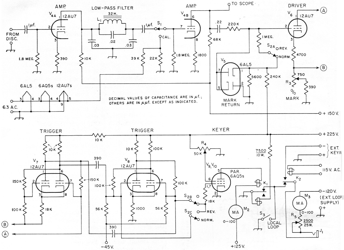
Fig. 2. Converter keyer circuit. Fixed resistors are ½ watt composition except as indicated. Capacitors with capacitance expressed in µF are paper; others may be either ceramic or mica. The control circuit (K2) and external keying terminals are used with associated f.s.k. transmitting equipment.
| J1 | Open-circuit jack. |
| K1 | Polarized relay (Sigma 7J0Z-160T). |
| K2 | A.c. relay, 115 volt coil, s.p.d.t. |
| L1 | 32 H at zero d.c., approx. 500 Ω (military surplus; suggested replacement, UTC type VIC-18 or VIC-19, or filter choke rated at approx30 henrys). |
| M2,M3 | 0-100 d.c. milliammeter. |
| R3 | 750 ohm composition control, audio taper. |
| R4 | 50,000 ohm wire-wound control, 4 watt. |
| R5 | 2500 ohm 25-watt rheostat (Ohmite H-0159). |
| S1 | S.p.d.t. rotary or toggle. |
| S2 | 3 pole 2 position rotary. |
| S3 | S.p.s.t. toggle. |
Keying circuits
The output of the trigger driver is direct-coupled to an Eccles-Jordan flip-flop stage, V7, which in turn is capacity-coupled to a similar flip-flop stage, V8. The flip-flop stages have two stable conditions, one of which results in a higher d.c. voltage across the load resistor than the other, and the stages are switched from one stable state to the other according to the polarity of the square wave of signal voltage from the trigger driver tube. The trigger output, taken from one or the other of the second-stage grids, is thus a keyed d.c. voltage, and is applied to the grids of the 6AQ5 keyer tubes to shift them between the conducting and nonconducting states.
In normal RTTY practice, the loop or locally-keyed circuit is closed during stand-by or mark signal. This keeps the machine in an idling condition to receive the coding pulses that key the loop circuit. The machine is keyed directly from the plates of the 6AQ5s in the CV-57, but in this unit we wished to key a separate loop circuit so a biased polar relay is connected in the plate circuit of the 6AQ5s. Because of the capacitive coupling in the amplifiers, no d.c. voltage is available from the signal to keep the output tubes conducting during mark or idling. Therefore, a "mark return" circuit is provided in the trigger driver stage for this purpose. In the "normal" position of S2, used when the signal shifts to the higher frequency in the mark or stand-by position, the grid of the trigger driver is four volts positive, setting the trigger stages to cause the 6AQ5s to conduct. The "reverse" position is used when the r.f. signal shifts to the lower frequency on mark. In this position of Sea the grid of the trigger driver is at zero voltage; this sets the trigger stages in the opposite state, but S2 simultaneously selects the trigger output of proper polarity to cause the 6AQ5s again to conduct.
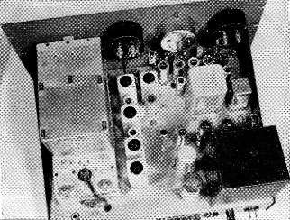
Top view, from the rear, of components on the 12 × 17 × 3 inch chassis. Power connections to the BC-453, at left, are made through the dynamotor socket on its rear deck. Between the 453 and the chassis wall are the output jack (which must be insulated from the chassis) and the loop current control, Rs. The external i.f. strip (Fig. 1) is alongside the 453, beginning near the rear edge of the chassis and running toward the front (top in this view). The 12AX7 scope amplifier is alongside the limiter, V2, with its controls, Re and R7, nearby on the chassis. The signal amplifier and trigger circuits (Fig. 2) are alongside the two right-hand meters. The large can in this area is the low-pass filter inductor, and to its right is the polar relay, Ki. Power-supply components are grouped on the near right-hand corner of the chassis.
The "per cent mark" control, a variable resistor in the cathode circuit of the trigger driver, Vs, is for adjustment of the operating bias for most linear amplification of the pulses in this stage. This is necessary because the pulse widths in the loop circuit must be the same as at the output of the discriminator to prevent loss of printing margin. This control, R3, is adjusted to give a symmetrical square wave at the plates of the 6AQ5s.
Discriminator alignment
For proper operation the output of the discriminator must be kept at a zero average; that is, the incoming signal must be tuned so that its mean frequency is centered in the discriminator characteristic. The tuning (assuming that the discriminator circuits have been properly aligned for a symmetrical characteristic) is checked by connecting a 50-0-50 microammeter in series with the one-megohm "threshold" (audio level) control, R2. This potentiometer limits the current through the meter as well as acting as an output control for the discriminator.
Most teletype transmissions operating at sixty words per minute use a shift of 850 cycles. It was decided, therefore, to adjust the discriminator to detect a shift of 425 cycles either side of center of the nominal 85 kc i.f.
First, it is necessary to have some sort of signal generator which can be accurately adjusted to shift the output frequency 425 cycles either direction. Most signal generators will reach the normal i.f. of 455 kc. Connect the generator to the input terminals of the converter and adjust its frequency to the i.f. of the receiver to be used. Tune the BC-453 to this frequency and peak the i.f. strip in the BC-453, including transformers T1, T2, and T3, for maximum d.c. voltage developed across the 1-megohm resistor in the grid return of T3 (see Fig. 1). With full limiting this shttuld be about -40 volts.Next, increase the generator frequency 425 cycles and adjust T4 for maximum positive output at Pin 1 of the 6AL5 discriminator, V3, using a v.t.v.m. with a zero-center scale. Reduce the generator frequency 850 cycles and tune T5 for maximum negative output. Adjustment of one transformer affects the adjustment of the other; consequently, alternate adjustments must be made as the frequency is shifted through 850 cycles to obtain equal and opposite voltages at Pin 1 of V3. It should be remembered that in f.s.k. the mark condition is high and the shift to the space condition is to a frequency 850 cycles lower. The 50-0-50 microammeter should show equal readings either side of zero. A smaller-range meter could very well be used for a more sensitive indication, but the one shown was already on hand.
For a more precise indication the vertical deflection circuit of the CV-57 scope monitor was built into the unit. The circuit is shown in Fig. 3. It obtains the deflecting signal from either the discriminator or the output of the second audio amplifier, whichever is selected by a push-button switch, S4, on the front panel. The circuit also provides an adjustable vertical centering voltage, by means of R7, when the deflection is taken from the discriminator. The external scope must have a 60-cycle sine-wave sweep and a balancing d.c. voltage must be applied to the second vertical deflecting plate to permit adjustment for linear deflection. For calibration and for a sensitivity check on the second audio amplifier and scope, a small 60 cycle voltage taken from the filament supply is applied to the grid of the second amplifier through Si, and the deflection from this voltage, when viewed on the scope, should correspond to 17 volts peak-to-peak at the plate of the second amplifier. Deflection by the discriminator output should be approximately the same, and can be adjusted by R6.
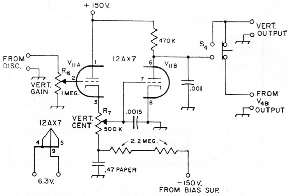
Fig. 3. Oscilloscope monitor vertical output circuit. Capacitances are in µF; fixed resistors are ½ watt.
| R6 | 1 MΩ composition control, audio taper. |
| R7 | 500 kΩ composition control, linear taper. |
| S4 | S.p.d.t. push-button switch. |
The power supply is a conventional regulated supply with the addition of a 6X4 rectifier to provide -45 volt grid bias to cut off the 6AQ5 keyer tubes, along with -150 volt for the scope monitor circuit. There is also a separate 125 volt supply using a selenium rectifier for the plates of the 6AQ5s.
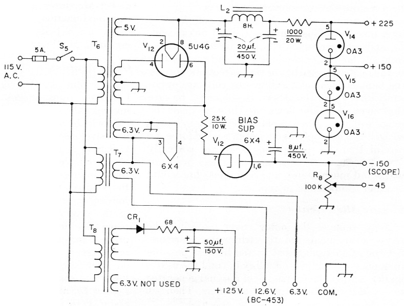
Fig. 4. Power-supply circuit. Capacitors are electrolytic.
| CR1 | Selenium rectifier 100 mA. |
| L2 | Filter choke, 8 H at 200 mA. (Stancor C-1721). |
| R8 | 100 kΩ composition control, linear taper. |
| S5 | S.p.s.t. toggle. |
| T6 | Power transformer, 540 volt c.t., 120 mA; 5 volt, 3 A; 6.3 volt, 3.5 A (Stancor PC8405). |
| T7 | Filament transformer, 6.3 volt, 3 amp. (Stancor P-6466). |
| T8 | Power transformer, 125 volt, 50 mA; 6.3 volt, 2 amp. (Stancor PA8421). |
The polar relay, a Sigma 7JOZ-160T, was used because of its compactness. The standard WE 215A may be used if chassis space permits. If desired, the polar- relay may be eliminated entirely and the printer magnets operated directly from the 6AQ5 plates, using the loop power supply with proper polarity. It will be found, however, that this is adequate for only one machine, while relay keying can be used for more than one - for example, a printer and typing-reperforator.
James L. McCoy, W0LQV/AF0LQV.