V.H.F. dummy loads
With everything made to work into coax these days, the need for nonreactive dummy loads is greater than it once was. You can't adjust a coupling system or check the efficiency of a transmitter correctly and legally without one. The old standby, the light bulb, is out for v.h.f. use. Poor enough on any frequency, the lamp load is hopeless in the v.h.f. range and higher. Its impedance changes with temperature at any frequency, and in the v.h.f. range the filament is likely to have resonances that make its brilliance unreliable as an indication of power output.
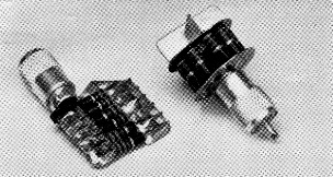
Two dummy loads made with carbon resistors. Six resistors are soldered to copper strips in the one at the left. The other uses a circle of resistors with copper disks to hold down lead inductance, and cooling fins to aid in heat dissipation.
Particularly in the low-power range, lamps are extremely poor loads for v.h.f. transmitter testing. Whatever their impedance may be, it is so far removed from 50 ohms that a coupling method that transfers power to a lamp load is almost certain to be far from right for use with low-impedance line.
Carbon resistors are usable, if they are connected in such a way as to keep leads to an absolute minimum. A single resistor inside a coaxial fitting will do for measurements that do not involve more power than the resistor is intended to handle. Noise generator terminations and resistive loads to simulate antenna conditions in receiver work are in this category. For transmitter use we need more power-handling capability than a single resistor will provide. There are noninductive resistors of high wattage on the market, but they are expensive and hard to find, so something like the loads shown here may be useful as inexpensive substitutes.
The wattage of a load made like these is limited by the number of resistors you can hook up in parallel without running the lead inductance up to a point where the noninductive character of the resistors is destroyed. Obviously the number of resistors could be extended considerably beyond what we have used here.
Low inductance is achieved by soldering the resistor leads to copper plates. The copper is also a good conductor of heat, and it keeps the resistors from overheating seriously when subjected to somewhat more than their normal dissipation for short periods.
The smaller of the two loads was made by paralleling 6 330-ohm 1-watt resistors. These are soldered to strips of flashing copper, which are in turn soldered to a coaxial fitting. The strip that goes to the inner conductor of the fitting was trimmed with tin shears to fit into the center contact of the fitting, rather than using a wire lead for this purpose. It is wrapped with plastic tape to prevent shorting to the sleeve of the fitting.
Using disks of flashing copper makes it possible to connect more resistors in parallel and still keep the inductance down. In fact, the disk construction of the larger unit makes it a more uniform load in the v.h.f. range than the one using the flat strips. A circle of 9 470-ohm resistors is shown, but 13 680-ohm or 19 1000-ohm 1-watt resistors could be arranged similarly, probably with equally good results.
While these are by no means perfect loads, they are good enough for most amateur purposes. Tested at 50, 144 and 220 Mc. they showed no greater than 1.2:1 s.w.r. At 50 Mc. they were extremely close to pure resistive terminations, and at 144 Mc. they showed only barely measurable reflected power when used within their power capabilities. As might be expected, performance was poorest at 220 Mc., but there they were far better than other inexpensive loads. In fact, in the past we have customarily used matched dipoles as loads at 144 and 220 Mc., because nothing around the ARRL lab was suitable for the purpose.
The wattage rating of the resistors should not be taken too literally. In a given batch of resistors there may be quite a range of ohmic value, and consequently the lower resistors will be dissipating more than the higher ones. You can solve this problem by selecting the resistors, but this was purposely not done with the loads shown. Suffice to say, the dissipating qualities of the copper plates and fins seem to be able to at least make up for the lowered cooling efficiency that results from putting a number of resistors in a confined space. The load with the disk plates and fins gets uncomfortably hot to the touch when it is run at 10 watts dissipation, but operating at this level for several minutes seems to have no bad effects. A stream of cooling air would raise the allowable dissipation considerably.
Normally a load will be used for only a minute or two at a time, just long enough to take a reading or two. For this work it is probably safe to subject the resistors to at least a 50 per cent overload. Check with an ohmmeter periodically to see that total resistance has not changed.