Transistor V.F.O. with linear tuning
Compact unit for mobile use.
The p.t.o. v.f.o. described in this article represents a significant departure from the conventional type constructed by most amateurs. Designed in this instance primarily for mobile use, it is, of course, suitable for other applications. Its linear tuning, extreme compactness, and low cost make it an attractive project.
For quite a few years now, the author has been building transmitters of one kind or another. Starting with the first small rig, all have been v.f.o.-controlled. With conventional a.m., v.f.o. requirements in regard to frequency drift are not too severe. However, the last couple of transmitters, designed for s.s.b., showed that the old v.f.o. had to go.
In designing a better v.f.o., there were considerations in addition to the one of frequency stability. A standard 180 degree dial of practical diameter provides less than 6 inches of scale for calibration. With a desired tuning range of 300 kc, a kilocycle occupies very little space on such a short scale. Also, the physical size of the v.f.o. units previously built was prohibitive for use with modern compact equipment.
The newest in the long line of transmitters was designed for mobile use and therefore compactness was doubly important. The panel space that could be devoted to the v.f.o. dial measured only 3½ by 2 inch. The problem of compactness was solved primarily by y making use of a transistor instead of a tube. The second problem of spreading the tuning range out over more than 180 degrees of dial rotation was overcome by turning to permeability tuning - Collins' bread and butter.
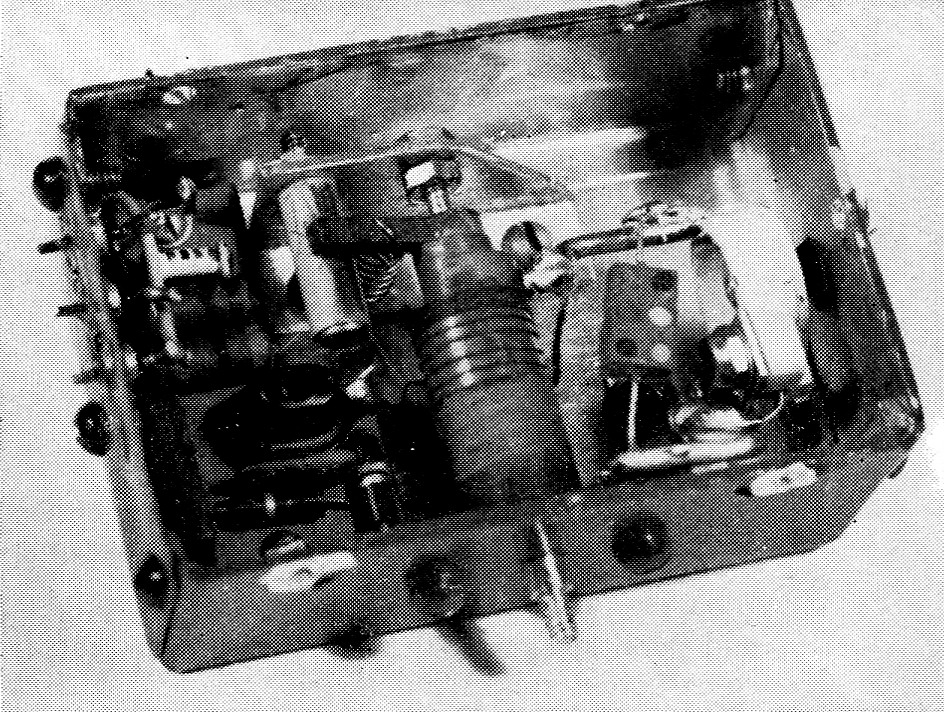
The complete v.f.o. is contained in a box measuring only 2_3/16 by 3_1/16 by 1_5/16 inch. The transistor subassembly is at the left, slug-tuned coil at the center, and the tuned-circuit capacitors at the right.
Circuit
The circuit of the v.f.o. is shown in Fig. 1. It is essentially the same as used by Landefeld in his transistorized receiver(1) (Pierce version of the Colpitts oscillator). A few small changes were made to assure more independence in respect to collector voltage and easier starting of oscillation. The tuning range is 2075 to 2375 kc (This signal is mixed with a sideband signal from a homemade 2900 kc crystal filter to produce a 4975 to 5275 kc signal. The latter is then mixed with a crystal-controlled frequency in the vicinity of 9 Mc to produce a sum which falls in the 20 meter band, or a difference falling in the 75 meter band.) By making suitable changes in tank-circuit values other frequency ranges within the frequency limitations of the transistor may be obtained. The transistor is the common and inexpensive 2N170.
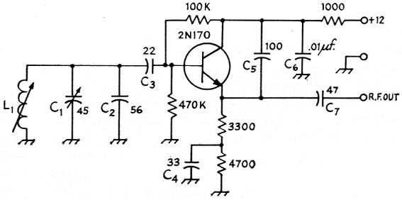
Fig. 1. Circuit of the permeability-tuned v.f.o. Unless otherwise indicated, capacitances are in pF and resistances are in ohm. Resistors are ½ watt.
| C1 | Ceramic trimmer, 7-45 pF, negative temperature coefficient (Centralab 822-BN). |
| C2 | 56 pF, silver mica. |
| C3,C4,C5,C7 | Mica or stable ceramic. |
| C6 | Disk ceramic. |
| L1 | See text. |
The variable inductor
The heart of the v.f.o. is the variable inductor, and the project was started with the fear that its construction might be beyond accomplishment with simple tools. However, this did not turn out to be the case.
The simplest mechanical arrangement for a variable inductor is the slug-tuned coil. So many factors have influence on the value of inductance (unavoidable variable capacitance is involved, too) that a prediction of the tuning curve in advance is a practical impossibility. However, with a little perseverance, the tuning curve can be adjusted experimentally to follow closely the desired linear shape when the required tuning range is small, as it is in this case.
The starting point of the construction is the selection of the slug to be used. The author removed the slugs from the core of a 455 kc i.f. transformer (capacitor-tuned type). These slugs are 3/8 inch in diameter and have a 1/8 inch hole through the center. The holes were threaded with a 6-32 tap. Adjacent ends of the two slug sections were coated with cement and threaded tight against each other onto a 6-32 screw while the cement dried.
The coil form is a piece of phenolic tubing having an inside diameter of % inch. To allow free movement of the slug inside the form, the slug, mounted on a screw, was chucked in an electric drill and trimmed down with a file.
The slug rides back and forth on a threaded lead screw. Turning of the slug with rotation of the lead screw is prevented by a threaded stop arm attached to the slug. The lead screw is made from a 2-inch 6-32 machine screw of brass. The head is filed off, and the opposite end is turned to a point in the electric drill. This point should have an included angle of slightly more than 45 degrees which can be easily estimated by eye. A 6-32 nut is then run onto the screw to a distance of 1% inches from the point, and soldered fast. The remainder of the screw beyond the nut is trimmed smooth to a diameter of 3 inch. This may be facilitated by filling the threads with solder before trimming.
Bearings and stop arm
The rear bearing for the lead screw is a short 6-32 screw fastened in a small bracket mounted toward the rear of the v.f.o. box (see interior photograph). The end of the screw is countersunk with a small drill and the tip of an ordinary countersink. Care must be taken to insure that this bearing is exactly centered on the lead screw and that the lead screw itself is perfectly straight. A bent screw or a bearing point off center will cause the slug to wobble and hamper resetability.
The author had some difficulty with the front bearing, which is simply a hole drilled in the front wall of the box. Looseness at this point will cause incremental shifts in frequency when the unit is shaken or banged. The problem was solved by increasing the size of the screw shaft at the bearing hole. This was done by forcing a piece of 3/16-inch o.d. metal tubing over the lead screw. The bearing hole in the box should, of course, be made as snug as possible, at the same time permitting smooth rotation.
The stop arm is a piece of 3/s-inch bakelite, shaped as shown in the detail photograph. The hole in this piece is tapped 6-32, and the arm is threaded as tightly as possible against one end of the slug before cementing it to the slug. This measure assures a secure grip on the threads of the lead screw to prevent backlash. The arm of the stop slides along a post mounted on the bracket supporting the rear bearing. The arm is held against the post by a spring anchored to the bottom of the bracket. Wearing of the threads of the slugs and consequent looseness on the lead screw can be minimized by a light application of oil on the screw.
The coil
The coil form, mentioned earlier, is 1_1/8 inch in length. The rear end of the form is notched out 1/8 inch for the stop arm, as shown in Fig. 2, leaving a winding length of 1 inch. This notch permits the slug to be moved completely within the coil winding.
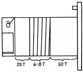
Fig. 2. Sketch showing approximate distribution of turns on Li. The notch at the left end of the form is to accommodate the stop arm as described in the text.
The coil form is cemented into a hole cut in a mounting base made of M%-inch phenolic which, in turn, is fastened to the front wall of the box with two machine screws. Sawed-off machine screws are used as terminals for the winding. One of these is tapped into the coil form at the rear end, while the other is tapped into the mounting base. Care should be exercised in placing the one in the coil form to make sure that it does not project inside the form and interfere with the slug. The inductance required for 2075 kc. is approximately 80 µh. No. 36 enameled wire was used, and the turns are proportioned approximately as shown in Fig. 2. In mounting the finished coil, every care should be used to align the coil form with the slug so that binding will not occur.
The remainder of the assembly of the unit is not critical. Mounting of the components in the small available space was facilitated by making a separate subassembly of the transistor and its associated resistors on a small strip of %/-inch bakelite.
Adjustment
Since the coil is a little difficult to work on after final assembly, a preliminary bread-board setup is advisable. Referring to Fig. 2, the adjustment consists essentially of changing the proportion of turns in one section of the coil, as compared to the number of turns in the other section, to get the right frequency spread with a chosen movement of the slug, and then adjusting the turns between the two sections to give the desired linear tuning curve. The two adjustments are not completely independent, of course, but the tuning ange needed is so small, and the movement of the slug so limited (3/16 inch) that a linear tuning curve is not difficult to obtain.
With the slug mostly out of the coil, trimmer capacitor Cr should be adjusted so that the frequency is at the high-frequency end of the desired tuning range. Then the slug should be moved into the coil by making 6 revolutions of the lead screw. If the resultant frequency is lower than desired, move a few turns from the larger section to the smaller section. If the frequency is too high, move a turn or two from the smaller section to the larger one. Since the slug may be moved 8 to 10 turns, a little experimenting will indicate which 6 turns most nearly approximate the desired turning range. Keep at least a half dozen turns in the space between the two sections of the coil. When the low end is on frequency, return the slug to its original position, readjust the trimmer, and repeat the process.
When the proper tuning range has been obtained, the frequency should be checked at intermediate points. Any nonlinearity can be corrected by movement of the spread-out turns between the two sections.
Six-turn stop
Fig. 4 shows the essentials of a stop for limiting rotation of the lead-screw shaft of the inductor to 6 revolutions. An extension shaft, coupled to the shaft of the v.f.o. inductor, carries 7 disks or large washers. The front disk is fastened permanently to the shaft, while the others are free to turn on the shaft. Each of the disks has a tab that will bear against the tab of the following disk. In Fig. 4, the shaft is shown in its full counterclockwise position, further turning in that direction being prevented by the tabs which have piled up against stop A.
Just before the first disk completes its first revolution in the clockwise direction, its tab will engage the tab of the second disk and carry the latter along with it. As the second revolution nears completion, the third disk will be picked up and so on until the last disk is picked up. At this point, the shaft will have almost, but not quite, completed 6 revolutions. The last revolution is short of completion by the combined thicknesses of the tabs. The second stop, B, limits rotation of the seventh disk to that necessary to complete the last full revolution. The front portion of the shaft should be supported in some sort of bearing. Stops A and B may be mounted on the front wall of the v.f.o. box or on a subpanel.
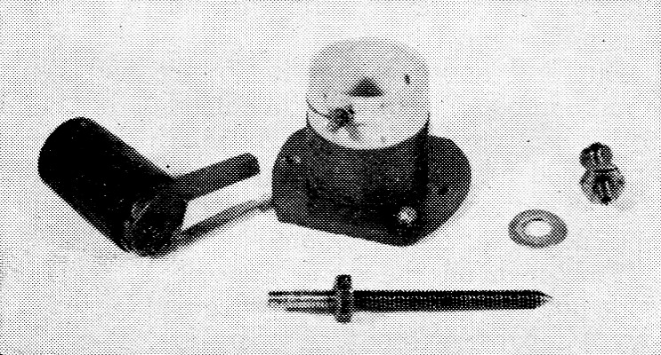
Essential components of the variable inductor. The slug with its stop arm is at the left, the coil attached to its mounting base at the center. The lead screw on which the slug rides is in the foreground. The washer is a thin one of the spring type. It is placed on the lead screw between the nut and the bearing hole in the front wall of the box.
After the lead screw of the inductor has been turned counterclockwise to its proper minimum-inductance end of the range (high-frequency end of the tuning range), the extension shaft should be turned counterclockwise until the tabs pile up against stop A, as shown in Fig. 4. The extension shaft may then be coupled to the lead screw.
Dial
The dial to be used with the v.f.o. is similar in principle to the dials used on Collins receivers and transmitters. Since it takes 6 revolutions of the tuning shaft to cover 300 kc, the coverage is 50 kc per revolution. A knob with a 1½ inch dial marked off in 50 divisions (1 kc per division) is attached to the shaft. A string-drive system couples the shaft to a small slide-rule scale which indicates the section of the band being covered with each revolution.
Calibration
The frequency range of this v.f.o. is outside the tuning range of many communications receivers, and the accuracy of calibration of receivers that do cover the proper frequencies is often questionable. For this reason, the calibrating arrangement of Fig. 3 was used. The signal from a stable oscillator or signal generator at 2725 kc and the signal from the v.f.o. are heterodyned in a 1N34 diode mixer. The second harmonic of the 350 to 650 kc beat, i.e., 700 to 1300, is fed into a calibrated receiver covering the broadcast band. Broadcast signals furnish marker frequencies, and the use of the second harmonic helps to improve the accuracy of calibration because the error in frequency measurement is divided by two.
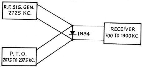
Fig. 3. Setup used in calibrating the v.f.o. as described in the text.
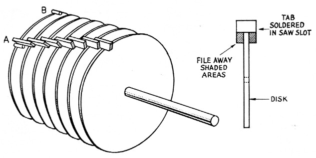
Fig. 4. Sketch showing the principle of the 6-turn stop. The shaft is shown in the full counterclockwise position. The disks may be large washers, the front washer soldered to the shaft, while the others just clear the shaft and are free to turn. The tabs are small squares of metal soldered into slots in the edges of the disks. The edge view of a disk, at the right, shows how the lower corners of the tabs should be filed away so that they will not interfere with adjacent disks.
When the 2N170 is oscillating, the circuit draws approximately 0.8 mA from a 12 volt source. Mechanical stability is about 100 cycles per three-foot drop to the floor, and thermal stability is less than 300 cycles over a normal temperature range. Changes of load on the output of the oscillator will cause small changes of frequency. However, a single buffer stage could be built right in the box with the oscillator and should eliminate this problem.
Although the project is a lot of fun just as an experiment, the oscillator is a useful stable unit and it should solve those tuning-mechanism problems that we run across in home construction. The parts are all easily available and cheap, which makes it desirable to those who must work on a budget.
Notes
Thomas H. Arnold, K7KCI.