A poor man's Q multiplier
Improving the selectivity of the BC-454 or 455.
In an earlier article on using the BC-454, a hint was dropped that there was a simple way of getting higher i.f. selectivity in these popular receivers. This is it. As old as the single-signal receiving concept, it's close to being a no-cost method of getting high selectivity.
The BC-454 is very popular both as an 80 meter receiver and as a tunable i.f. in a multiband receiving arrangement, as the response to recent articles(1) in QST has proved. Those interested in getting a lot of selectivity, with minimum cost and effort, from the 454 will find the "poor man's Q multiplier" described in this article a very simple way to do it.
The circuit, with "before" and "after" details, is shown in Fig. 1. All that is required is the addition of a 5000 ohm variable resistor, R1, and a capacitor, C1. The circuit change consists of lifting the cathode resistor of the 12SK7 secondi.f. tube from chassis ground and inserting the 5000-ohm resistor as shown. C1 is made from two short lengths of insulated wire. One piece is connected to the grid terminal on the tube socket and the other to the plate terminal. The other ends of the wires are left open; thus the two wires serve as a coupling capacitor between the grid and plate circuits of the second i.f. stage. When the 5000 ohm resistor is varied the i.f. stage can be made to oscillate. At the point just below oscillation the over-all selectivity of the receiver is considerably improved. In fact, the selectivity approaches that obtained with much more elaborate circuitry.
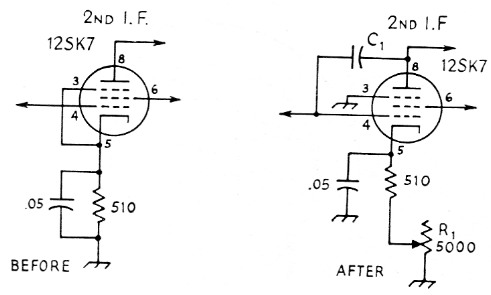
Fig. 1. Circuit diagrams before and after modification of the second i.f. stage.
| C1 | See text. |
| R1 | 5000 ohm potentiometer. |
How to do it
Fig. 2, a bottom-view layout drawing of the receiver, will help in identifying the proper tube socket. After taking off the bottom plate, remove the two screws that hold the potted capacitor directly over the second i.f. tube socket. It isn't necessary to unsolder the lead to the capacitor; there is enough lead length so the capacitor can be laid to one side, leaving plenty of room to work at the socket.
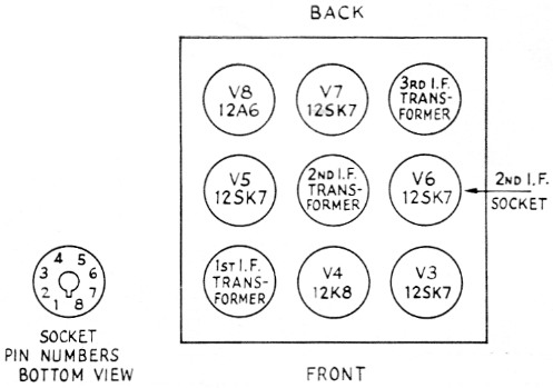
Fig. 2. Layout diagram (bottom view) of the receivers showing locations of tube sockets and i.f. transformers.
Remove the jumper wire between Pins 3 and 5 and ground Pin 3 to the nearest chassis ground connection. Locate the cathode resistor, which is on the mounting board immediately to the rear of the tube socket. The resistor, 510 ohms (greenbrown-brown), should be the first unit, nearest the tube socket. One side of the resistor is connected to the cathode terminal, Pin 5, and the other side goes to chassis ground. Unsolder the end of the resistor connected to ground. The simplest method of doing this is to hold the lead with long-nose pliers and heat the connection, then when the solder melts pull up gently on the lead and it will come out of the terminal.
If you have your receiver mounted on a separate chassis as described in the January, 1959, QST article, the 5000 ohm resistor can be installed on the chassis. If not, a small right-angle bracket can be mounted on the side of the receiver case to hold it. Once you decide on the mounting, all you need do to complete the installation is connect a lead from the ungrounded end of the 510 ohm resistor to the movable arm of R1 and connect one fixed terminal of R1 to chassis ground.
The feedback capacitor, C1, consists of two pieces of insulated wire (any convenient gauge) approximately ¾ inch long. Solder one wire to Pin 4 and the other to Pin 8. Position the two so they are parallel to each other and about inch apart. Make sure the free ends of the wires aren't touching anything.
Adjustments
Use a clip lead to connect the case of the potted capacitor to chassis ground temporarily.
The feedback capacitor, C1, may require adjustment and it is easier to do with the capacitor out of the way.
Apply power to the receiver and let it warm up. Set R1 so all the resistance is in the circuit. Next, adjust the b.f.o. trimmer so that the background noise has a high pitch. The trimmer control is the small screw in the square box mounted on one side of the receiver near the rear, and is accessible from the side of the case. Only a slight adjustment of the screw should be required.
Next, tune in a c.w. signal. Slowly decrease the resistance of R1 and you should find a setting where the i.f. stage will go into oscillation. This will be indicated by a howl. Set the control just below the point of oscillation and tune the receiver across the signal. You should find a tuning dial setting where the signal peaks quite sharply. In addition, as you tune through the signal from one side of zero beat to the other, you'll notice that the beat note on one side is much weaker than on the other.
If you find that you cannot get the conditions just described or that the i.f. cannot be made to oscillate regardless of the setting of the resistor, try moving the wires forming C1 closer together. Once you get the correct setting you can remount the potted capacitor, making sure the open ends of Cl aren't shorting to the capacitor case.
The modifications described here were tried on both the BC-454 and 455 with equally good results. For the very small expense and labor - the modification only takes about an hour and a half - it is pretty hard to find a better method of improving the performance of these popular receivers.
One final tip: Keep the receiver gain down so the signals arriving at the second i.f. stage aren't too strong. The regeneration in this stage will build them up to normal strength. The more you depend on the regeneration for gain the better the selectivity.
Notes
- McCoy, "Getting started with the BC-454," QST, January, 1959.
McCoy, "80 through 6 with the BC-454," QST, May, 1959.
Lewis G. McCoy, W1ICP.