Amateur V.L.F. observation
How to listen for whistlers.
About whistlers
Though the eerie radio noises discussed in this article were first discovered in Austria in 1886, and thus are among the oldest known radio phenomena, probably few amateurs have ever heard of them, much less listened for them. A report of a 6-year inrestigation of the phenomena was published in 1893, but this work was gene ally overlooked until very recently. The German scientist Barkhausen rediscovered whistlers while eavesdropping on Allied telephone conversations during World War I. He thought them something new, and gave the descending tones he heard their descriptive name.
Observation of whistlers assumed scientific importance when they were recognized as evidence of propagation of radio waves of very low frequency along the lines of flux of the earth's magnetic field. The principal source of whistlers is the electromagnetic energy radiated from lightning discharges. Though propagated as a radio wave, its frequency overlaps the audio range, and the "signal" can be heard simply by picking it up on an antenna and applying it to a headphone.
With more sensitive equipment, atmospherics (commonly called sferics) can be heard by dispersive propagation from halfway round the world. As the speed of propagation in a dispersive medium is a function of the wave frequency, a note of descending pitch is heard when the low frequencies in the sferic travel slower than the higher frequencies, and consequently arrive progressively later. It can be seen that here is a means of determining path length, and from this it was learned that whistler propagation is by A route far out in space beyond that of normal ionospheric propagation.
All manner of interesting possibilities are suggested by this hypothesis. A full discussion of whistler theory is beyond the scope of a QST presentation, but references are given for those who wish to pursue it further. Meanwhile, here is information on how to listen for whistlers. The author has been working in this field for several years at the Thayer School of Engineering at Dartmouth College, one of the centers of whistler research. The extensive program there is under the direction of Dr. M. G. Morgan, W1HDA.
Editor
With most eyes turned these days toward the glamour of jets, rockets and satellites, speculation on space beyond the earth is growing by leaps and bounds. At the same time, to a world accustomed to electromagnetic propagation below the ionosphere, the idea of propagation through and beyond it is a fascinating one. Thus a paper by Storey on whistling atmospherics,(1) presented to the URSI Assembly in Australia in 1952, attracted wide attention in the scientific world - particularly that part of it in North America.
Articles appearing in the technical literature about the work done and to do in the field of whistler propagation(2) have served to excite the curiosity of amateurs with scientific interests. In recent months it has become quite apparent that the challenging ideas presented have inspired many an attempt to receive signals in the v.l.f. region, transmitted by this type of propagation. While much has been published on theoretical considerations, practically nothing has appeared in print that is of use to the amateur.
Equipment requirements
Since phenomena of this type have a frequency range within the hearing of most humans, all that is absolutely essential in the way of equipment is some means of amplifying the faint signals received and changing them into sound. A wide-band audio amplifier with a gain of 130 dB, a pair of phones, and 200 feet or so of No. 12 wire meets the minimum requirements nicely. As might be expected, there is a considerable gap between this minimum and what is satisfactory from a research point of view.
To receive these v.l.f. signals some kind of antenna must be used. Three general types are common: long horizontal or gently-sloping wires, from 100 yards to several miles long; verticals, from 30 to over 100 feet high; loops, from 200 turns a meter square, to the single-turn monster hanging across a Colorado canyon. All have been used in whistler research, and all are capable of detecting signals satisfactorily.
Any one antenna will, in general, be something of a compromise. Long wires have excellent pickup, but the nasty habit of responding easily to precipitation static, man-made noise and r.f. fields. Vertical whips, while easier to put up, have smaller pickup and can be dangerous in electrical storms. Loops are relatively free of these troubles, but are extremely subject to interference from stray fields, which exist in amazing strength near civilized areas!
Since most amplifiers use either vacuum tubes or transistors, the problem of coupling the antenna to the input of the amplifier is next in order. Long wires and whips are easily coupled to the high-impedance grid circuit of a vacuum tube, but they are somewhat awkward to use with transistors. A ten-foot square loop of 100 turns or so can be coupled directly to a transistor, but is unbalanced, and usually has a resonant frequency low enough to be troublesome. A 40 foot square loop of 20 or so turns is fine, but far too heavy to put up, while a similarly-sized one of two or three turns, though easy to erect, has such low impedance that some sort of transformer is needed to match it to anything!
The-IGY whistler programs at Stanford University and at Dartmouth College use triangular loop antennas about 40 feet per side. They drive a transformer of approximately 1 to 250,000 ohm step-up. This means that the distance between loop and amplifier must be small, and that the loop and transmission line be of low resistance compared with the 1 ohm primary. The Triad Transformer Corporation and Jobbins Electronic Enterprises have made transformers especially for this purpose, and it is quite possible to use a velocity microphone transformer, taking possibly a small loss in signal by so doing. To match such a loop to a transistor, a different ratio (1 to 1000 ohm, for example) would be used. At the present state of the art, special audio tubes seem to be quieter than transistors, so as far as equipment noise is concerned, it is preferable to use a low-noise audio tube such as 12AY7 for the first stage or stages. However, in many areas local noise is so high that nothing is to be gained through use of these special tubes, and high-gain audio pentodes, triodes, or even transistors are perfectly adequate.
The antenna should be placed as far from occupied houses, power lines, TV sets, etc., as possible; 100 yards at least. Since the amplifier will usually be near the antenna it will be subject to the vagaries of weather, indicating need of a weatherproof shelter. At this point, one great disadvantage of transistors becomes important. It is difficult to design transistor circuits to have constant gain over a wide range of thermal conditions, but vacuum tubes present no problem at all. When equipment must be designed to operate it such extremes as the Equator (Huancayo, Peru) or the poles (Antarctica, Greenland), vacuum tubes offer very definite advantages in spite of their inherent inefficiency, and thus are at present standard in whistler equipment.
Getting ready
A circuit which represents the latest thinking at Dartmouth is shown in Fig. 1. It has quite enough gain, and is fairly simple to build in a 4 × 5 × 6 inch box. Great care should be used in layout and wiring to prevent coupling from output back to input, or oscillation will inevitably occur. When made carefullly, it cannot be made to oscillate without external pickup. By using a 500-ohm balanced output, it is possible to run a long signal line back to the warmth and comfort of one's home, where the signal can be applied through a 500 to 20,000 ohm transformer to a pair of crystal headphones.
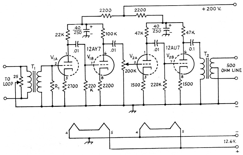
Fig. 1. Basic amplifier for whistler reception. Capacitor values in µF; those with polarity marked are electrolytic. Resistors 1 watt.
| R1 | Depends on T1, in this instance it is 270,000 ohm. |
| T1 | Special input transformer, 1 to 270,000 ohms (Triad 40133). |
| T2 | Output transformer, 20,000 ohm to 500ohm line (Triad HS-50). |
A well-filtered high-voltage source of 150 to 200 volt d.c. for the plates is needed, and 12.6 volt d.c., reasonably well filtered, is also desirable for the filaments. It is possible to use a.c. on the filaments, but it is far from desirable. A typical power supply is shown in Fig. 2. When installing the power supply near the antenna, field leakage from the transformer may get into the antenna, and unnecessary hum results. Use of high-quality components and careful orientation of equipment near the antenna will keep this hum to a minimum.
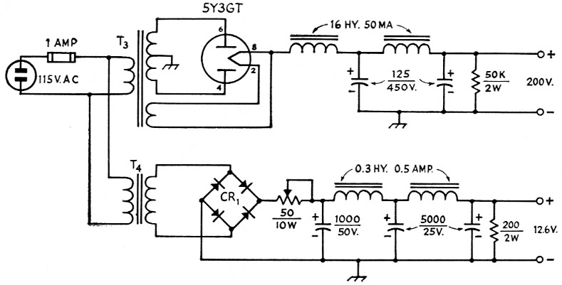
Fig. 2 D.c. supplies used with the whistler amplifier. All capacitors are electrolytic; values in µF.
| CR1 | Full-wave rectifier, 36 V a.c., 0.5. A |
| T3 | Plate transformer with 5 volt filament winding; to give 200 volt d.c. at 50 mA through filter (Triad R-6A). |
| T4 | Filament transformer, 115 volt primary, 24 V 1 A secondary (Triad F-40X). |
The next step is to set up the antenna system, which, like that of many radio stations, is the most important element of the entire operation. For easy erection of a three-turn triangular loop, we need a 40-foot pole with a pulley on top, 80 feet of rope and 150 feet of three-conductor plastic sheathed No. 12 cable. The pole should be well removed from utility lines (especially those of 2300 volts or more) and associated transformers. Tie the rope to the middle of the 3-conductor cable and haul it to the top of the pole. Bring the two ends of the cable together at the base of the pole, and connect them so that there are three turns in series: solder left-hand white to right-hand red, and left-hand red to right-hand black. The two remaining ends, left-hand black and right-hand white, should be connected to the input transformer of the amplifier. The loop should then be pulled out into an isosceles triangle with base parallel to the ground, and for convenience, about 3 feet above it, as in Fig. 3.
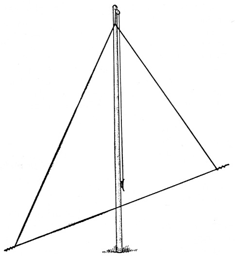
Fig. 3. Loop antenna used for whistler and other v.l.f. reception. Three-conductor cable is connected in series to form a 3 turn loop. Apex of the triangle is made by hauling the antenna to the top of a 40 foot support on a halyard. Loop must be oriented for minimum hum pickup in locations near to built-up areas.
Interference problems
The great moment has now arrived! Apply power to the amplifier, put on the headphones, and await results. Except in rare cases of extraordinary good fortune, the results will be a tremendous roar of odd harmonics of the 60-cycle power lines, punctuated by the defies of summertime static perceptible in the background. If such indeed is the case, the aid of two pairs of patient, if not necessarily willing, hands is required. Physical strength is not required, so the wife and number one child, brothers, sisters, or even the attractive girl next door will do - just any two people who can be persuaded or coerced into furthering scientific discovery for the good of society will be quite satisfactory.
Have these two assistants grasp the two lower vertices of the triangle made by the cable, and while keeping in a plane through the pole, walk slowly about it, first in one direction, then in the other, as directed by the chief engineer, who is diligently listening while this is going on. There should be one direction where the worst of the hum disappears, if not all of it. At this point, small careful adjustment of the input balancing pot may improve things.
If no position of the loop produces a distinct minimum in hum, and if the hum consists only of the lower-order harmonics (780 cycles or less), then the installation of a high-pass or band-pass filter, designed to cut sharply just above the highest interfering harmonic, may save the day. If, as far too frequently happens, the hum has strong 60 cycle harmonics to 2 kc and beyond, then you've just about had it for that particular location at least. At this point, there are two courses of action: (1) move to a new location, and try again or (2) give up the whole idea!
What to listen for, and when
Suppose for a moment that the unusual has happened and all went well; luck is with you, and hum is down enough to hear tube noise. Tie down the loop in the position for which hum is a minimum, and then listen carefully for strange noises in the audio range. You will listen hard, yes, very hard, to hear the strange noises mentioned in those exciting articles. So it might be well at this point to consider just what the expected phenomena are like.
The v.l.f. phenomena for which we are listening are broadly classified into two main groups: (1) whistlers; (2) ionosferics. Whistlers are believed to be the result of some of the electromagnetic energy released by an impulse of atmospheric electricity being propagated through the ionosphere, following a path taking it thousands of miles from the surface of the earth, and being greatly modified in character during its course. lonosferics are believed to be the result of some electromagnetic energy, originating within or beyond the ionosphere, traveling through the ionosphere and being modified during its travels.
A whistler is most frequently not a clean-cut whistle, but rather a broad band of noise something like hiss, which descends in frequency with time. An approximation can be made by mouthing the sound "ee-you" while hissing instead of vocalizing.
The other category, ionosferics, turns out to be something of a catchall, and is subdivided much further. The most common of these in occurrence in New England stations is called hiss and dawn chorus. Hiss is just as its name implies - a sound like compressed air escaping through a small vent, while the name dawn chorus was given by the British, to whom the sound is like that of birds before sunrise. To most Americans, the sounds made by spring peepers are quite similar, so the name frog chorus might be more descriptive. There are many more sounds in the category of ionosferics, but a description of them would read somewhat like lurid science fiction, quite inadequate for the uninitiated and unnecessary for the experienced listener.
Setting up the loop was probably done on some pleasant summer week-end morning so the probability is very strong that nothing exciting will be heard; that is nothing more than the snap - crackle - pop of summertime sferics. A session of listening to this program material is frequently enough to cause the budding scientist to go back to the peace and comfort of the hi-fi in the living room. The more hardy, undaunted by the disappointing racket, may even have courage enough left to try listening after supper, only to find the barrage of snap - crackle - pop not only still there, but even more overpowering than before. Those with skilled and toughened ears may be able to note a slight change in the character of certain sferics after sundown. Some sferics, through reflections from the ionosphere, have a musical character, similar to the sound of a bullet flying closely overhead. Still, most probably there will be no whistlers, no ionosferics; nothing except racket!
About this time, there may well be some muttering of "fake," "gyp," etc., but let's see why. At those stations operated by Dartmouth, it has been observed day in and day out (or, more precisely, night in and night out), month in and month out, that whistlers are owlish in habit, occurring mostly at night, starting up usually shortly before local midnight, and continuing until after local sunrise. During the winter months, whistler activity is quite small compared with analogous summer months. Ionospherics, on the other hand, show more activity in winter; less in summer.
This is typical for east coastal North America from Washington to the St. Lawrence. North and south of this region, there seems to be a different pattern, the nature of which is not as yet fully understood.
From the incidence of whistlers at W1FGO, it is fairly evident that in order to hear this activity at all consistently one will either lose a lot of sleep, become something of an owl oneself, or adopt some means of automatic sampling via recordings. At this point it must be obvious that something a great deal more complicated is required for extensive work.
Automatic sampling and recording
To engage in a program of systematic sampling of these phenomena poses problems which take the business quickly out of the hands of most amateurs and dump it squarely into the ample laps of the professionals. Precise timing of samplings is not of prime importance for general studies of ionosferics, but for studies of whistlers it is of utmost importance. The equipments in use at W1FGO and W1HDA use Western Electric 100-kc. crystal standards, driving laboratory-built countdowns to cycle as slowly as once in 10,800 seconds.
This clock (and it is a clock, albeit somewhat difficult to tell time by!) has operated without need for adjustment, within 0.05 seconds of WWV and CHU for over 50 days at a time ! A good but less precise approach is to record WWV or CHU simultaneously with the signals received. In this way, time is as good as could be desired, provided only that WWV or CHU can be heard reliably.
Apparatus as used at the Dartmouth stations is designed to program automatically every 30, 60 or 180 minutes. At 35 minutes past each hour, it starts up a tape recorder, applies a 1 kc calibration tone for 2 seconds (length of tone is shorter every third hour), superimposes an 8 kc tone on the recording every second, and a 7.5 kc tone every tenth second. At the end of 110 seconds, the signals are muted, and the recorder then records 5 seconds of blank tape, after which the program comes to an end, to be repeated again on the next schedule.
Should anyone wish to maintain a similar schedule (there is now a possibility of changing the time of recording to 50 minutes past each hour), I would be very glad to compare information, as regularly-recording stations are scarce on this continent, being largely confined to the coastal areas. In North America, Stanford University is operating stations at Kotzebue, Anchorage, College, Unalaska (all in Alaska), Seattle and Stanford. They are also cooperating with the CRPL station in Boulder, Colorado. Dartmouth College is currently operating stations at Frobisher Bay, Northwest Territories; Knob Lake and Mont Joli, Quebec; Dartmouth; Washington, D. C.; and Bermuda. The Canadian government has stations at Saskatoon, Ottawa, and Halifax. Information from areas not close to those mentioned would be most welcome.
A final word of warning is in order. The U. S. Navy operates several v.l.f. transmitting stations: NSS near Washington; NLK, the colossus of Jim Creek, now keyed via HF link from San Francisco under the call NPG; and NPH in Hawaii, not to mention several others operated by other nations, all on frequencies from 15 to 25 kc. It is a sad fact of tape recording that considerable boost per octave is applied to material beginning at 6 kc or so before applying to the recording head. With strong signals existing on, for example, 15.5 kc, the 20 dB and more boost given this frequency range saturates the tape, causes cross modulation with other signals, and frequently produces enough harmonics to mix efficiently with the bias frequency of the tape recorder.
Thus, in practically every installation where a tape recorder is to be used, it will be necessary to install a filter somewhere in the system to attenuate these v.l.f. signals to a point where they are harmless. At a low level they are actually beneficial, for they form a means of checking the time at which events occur at various stations.
A tape has been prepared at Dartmouth containing some samples of the phenomena heard in this area, for use in helping identify various phenomena. Until it gets to be too much of a nuisance, the author will, for the price of the postage, lend it out to groups or interested individuals.
Notes
- Storey, L. R. 0.: An Investigation of Whistling Atmospherics, Phil. Trans. Roy. Soc., A., Vol. 246, pp. 113-141, July 9, 1953.
- Morgan, M. G. and Helliwell, R. A., Atmospheric Whistlers, Proc. IRE, Vol. 47, No. 2, Feb. '59, pp. 200-208.
W.C Johnson, W1FGO.