High-level balanced modulator for D.S.B.
Making use of your present A.M. rig.
Here's an easy way to get rid of your carrier if you want to mingle with the "sidebanders." Using the modulator output of your present transmitter, it puts just the same power into sidebands as a.m. does, but without the carrier that causes the heterodyne howls and squeals.
Many fellows who are operating on a.m. would like to take a fling at "sideband" but in many cases the economic situation prevents it. The method proposed here allows the use of the present plate modulator, and uses the final stage of the existing transmitter as a driver for an adapter unit for carrierless double-sideband transmission. Transmitters such as the Viking Ranger, Globe Champion, Vikings 1 and 2, Lettine, DX-100 and Valiant can easily be adapted to this method of communication.
In double sideband without carrier, both the "positive" and "negative" parts of the modulation envelope are filled out with r.f. of high amplitude as shown in Fig. 1. The secret of the conversion to d.s.b. is to shift the phase of the r.f. 180 degrees on the negative voice swings. Thus the positive voice peaks give an envelope which is of one r.f. phase and the negative half cycles give an envelope in the r.f. which is 180 degrees out of phase. At the receiving end, a carrier is injected (from the b.f.o.) to replace the carrier that is not transmitted. If this injected carrier is in phase with the original suppressed carrier, the r.f. pulses representing the positive swing of modulation will add to the injected carrier, giving an increase in detector output. The r.f. pulses that are 180 degrees out of phase will subtract from the injected carrier, decreasing the detector output. Thus, the phasing of the r.f. pulses causes exactly the same effect at the detector as the positive and negative swings of the modulation envelope of an a.m. signal, providing carrier injection is used at the receiving end.(1)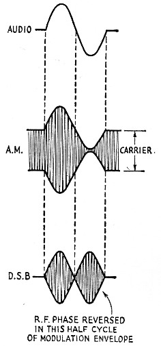
Fig. 1. The difference between amplitude-modulated and carrierlessdouble-sideband signals is illustrated by these drawings.
Both s.s.b. and d.s.b. use balanced modulators to accomplish the phase shift, along with carrier suppression. In addition, the s.s.b. generator uses filters or additional phasing networks to eliminate one sideband.
Double sideband can be generated at a low level and amplified through linear amplifiers. However, there is no reason why it cannot be generated at any desired power level.
General method
One method of generating d.s.b. is to use a pair of tetrodes or pentodes in a balanced modulator with the modulating voltage applied in push-pull to the screens. This method uses a fixed plate-supply voltage and varies the plate efficiency and plate input at an audio rate.
The method to be described, on the other hand, uses the output of an a.m. modulator to supply audio-frequency plate voltage to a high-level balanced modulator. No d.c. plate supply is used and the power output of the audio amplifier is the factor that determines the input to the final stage. A modulator that is capable of modulating a Class C stage input of 200 watts will have a rated average power output of 100 watts on a sine-wave basis. This equivalent to a peak output of 200 watts, thus such an audio amplifier will furnish about 200 watts peak-envelope input power to the balanced modulator. Modulators used with a single 6146 final tube usually have outputs of about 30 watts average audio power; these jobs will give about 60 watts peak output.
A balanced modulator always requires push-pull audio, and modulation transformers do not often have center-tapped secondaries. This difficulty can be overcome by using auxiliary rectifiers arranged, with the balanced-modulator tubes, in what is essentially a bridge circuit so that both the positive and negative voice peaks will cause positive audio voltage to be applied to the balanced-modulator plates. Referring to the practical circuit diagram of Fig. 2, when the top end of the secondary of the modulation transformer, T1, goes positive, the plate of V1 is driven positive, with the ground return circuit through rectifiers CR3CR4. On negative voice peaks (bottom terminal of the transformer secondary positive with respect to the center tap between the rectifiers) the plate of V2 is driven positive, with the return through CRICR2. Thus positive voice peaks supply the power for VI and negative voice peaks supply the power for V2.
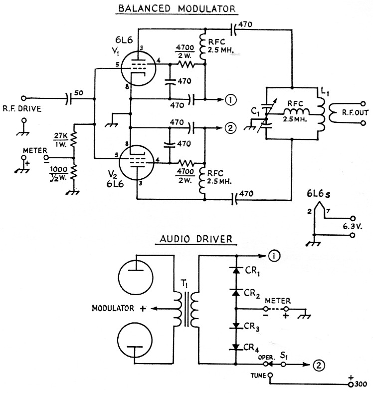
Fig. 2. A practical adapter circuit, in this case built to utilize the audio output of the modulator in a Viking Ranger. Other types of tubes may be substituted in the balanced modulator, if desired, the principal requirement being that they be capable of handling the average power output of the modulator without overloading. A safe figure for average output of the modulator is one-half the d.c. input to the modulated stage in the trcnsmitter in which the modulator is incorporated.
Capacitances in the figure are in pF; either ceramic or mica bypass capacitors of suitable voltage rating may be used (see text for peak-voltage data). L1 and C1 comprise a push-pull tank circuit that should meet ordinary standards for Q on the particular band used. Suitable components are suggested in the text.
The 300-volt supply is used only for tune-up; the voltage is not critical. St may be a s.p.d.t. toggle at voltages up to 500 or so.
If V1 and V2 are driven at r.f. with their grids in parallel and their plates in push-pull, as shown in Fig. 2, we have a balanced modulator. Both grids are driven in the same r.f. phase, but the plate outputs of the two tubes are in opposite phase because of the push-pull output connection. (If plate voltage is applied to the two simultane ously, the output at the frequency applied to the grids is zero because of this opposite phasing. This eliminates the carrier at the output.) However, when the audio voltage is alternately applied to the plates of V1 and V2 the resulting alternate outputs have opposite r.f. phase, giving the type of envelope shown in the lower drawing of Fig. 1 Because the power supply is at audio frequency and because of the bridge system, only one final tube can work at a time.
No special neutralization is necessary with this method of operation because the nonfiring tube is in effect a neutralizing capacitor for the tube in operation. Thus triodes, tetrodes or pentodes can be used in the same basic circuit, the only difference being in the driving requirements.
A typical adapter
The adapter shown in the photograph, using the circuit of Fig. 2, was built to be used with a Viking Ranger, T1 being the modulation transformer in the Ranger. However, the same general method can be used with any transmitter having plate modulation. The choice of tubes to use in the balanced modulator will depend on the capabilities of the modulation system. Most of the popular transmitters use beam tetrodes as the modulator tubes, and as a general rule, the same type tubes can be used in the final as are used in the modulator. Thus, if the modulator uses type 6L6 or 1614 tubes, then the balanced modulator can also use 6L6s or 1614s. If 6146s are used in the modulator, the same type tubes can be used in the adapter.
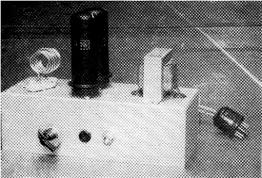
The W8NJH adopter unit for d.s.b. is suitable for use with transmitters running up to 75 or 100 watts plate input on a.m. Since the adapter uses only audio voltage from the modulator in the "parent" transmitter, no d.c. plate supply is necessary for regular operation. The filament transformer shown on the chassis is needed only if the heater supply in the existing transmitter is not able to supply the extra power.
The pin jack is for measuring grid current; other controls are the plate tuning and a tune-operate switch. The construction may be varied to suit the tubes and other components that may be chosen; attention to ordinary good practice in laying out a push-pull circuit is all that is required.
The screen and plate are modulated simultaneously with this method. The screen resistors are selected to cause higher plate current than with regular a.m. operation. Thus, if a screen resistor of 30,000 ohms is used in an a.m. rig having a 6146 final, a resistor of about 15,000 ohms would be used with this method. This offers a heavier load to the modulator, but will not harm the tubes because of the low duty cycle, which cannot exceed 50 per cent for either tube in the final amplifier.
Audio rectifiers
A number of concerns are offering germanium and small silicon rectifiers having an inverse peak voltage rating of about 400 volts. In the bridge circuit of Fig. 2 the peak inverse voltage across the rectifiers in one leg is equal to the peak voltage developed in the secondary of T1. This peak voltage will at least equal the d.c. voltage applied to the modulated r.f. amplifier in the original transmitter. Thus if the plate voltage on the Class C final is 600 volts, the inverse peak voltage also will be 600 volts and two 400 volt p.i.v. rectifiers should be used in series in each leg. If the d.c. voltage on the modulated final is between 800 and 1200 volts it will be necessary to use three rectifiers in series in each leg.
The current rating required of an individual rectifier can be taken to be equal to one-half the d.c. plate current of the modulated Class C stage in the transmitter. If the modulated final takes 150 ma., for instance, the individual rectifiers need only have a current rating of 75 mA.
Tube rectifiers could also be used for this type of service but the semiconductor rectifiers eliminate the need for filament transformers and have proved to be very efficient.
Tank circuit
The unit shown has been used on all bands from 160 down through 6 meters. If you want to operate on only the higher-frequency bands, a dual 35 pF capacitor will do for C1. If you want to cover 80 through 10, then a dual 100 pF unit should be used. With only 500 volt developed on peaks, even the spacing used in broadcast capacitors can be used. Standard 25-watt plug-in push-pull type coils such as the B & W MCL series can be used for the tank coils.
Metering
If you want to measure both grid current and plate current you can build the meters into the adapter. The grid-current meter can be connected between the top of the 1000-ohm resistor in the grid circuit and ground. A plate meter could either be inserted in the 300 volt test lead or inserted between the rectifier center tap and ground. If you have some sort of r.f. output indicator, such as an s.w.r. meter, permanent meters are not necessary. All that is needed is to tune the Ranger (or other type transmitter) for proper grid current in the adapter and then tune the plate circuit LiC1 for maximum output as indicated on the s.w.r. meter. A common multimeter can be used to measure the grid current.
Using the adapter
Connect a length of coax from the output terminals of your present rig to this adapter. Since the driving power required is quite small, the tube or tubes in the final of your present rig will be loafing. Adjust the output coupling so that you get a grid current of about 1 to 2 mA in the adapter. At this point, the plate current of the final in your present rig will be close to minimum. Excessive drive gives no more output and does not allow as much carrier suppression because of stray feed-through, which will be proportional to drive.
The double-throw switch, S1, is used for tune-up purposes. After you have obtained a milliampere or so of grid current, throw the switch to the "Tune" position, which supplies 300 volts to only one of the tubes, and adjust C1 for maximum output. This indication should be on some form of r.f. output meter, for ease of tuning. (Note: Be sure to turn Si to the "Operate" position before shutting off the r.f. drive; this will prevent burning up the screen in the tube.) With the switch in the "Operate" position, talking into the microphone will cause audio voltage to be supplied to your adapter and you are on double sideband.
Reports have indicated that the voice quality and carrier suppression of this little rig are excellent. Tests have shown that the peak-envelope output on 75 meters is about 40 watts when used with the Viking Ranger. The output of an adapter using 6146 tubes with a Valiant should be about 200 watts peak.
One note of caution: if you do not have an extra-stable v.f.o., use crystal control. By keeping your frequency extremely stable you are giving the fellow at the receiving end an extra break.
Notes
- The requirement that the carrier injected at the receiver be in phase with the carrier suppressed at the transmitter is a severe one and a highly specialized detection system is necessary for meeting it. However, if one of the received sidebands is rejected in the receiver so that the incoming signal is converted to s.s.b., ordinary s.s.b. reception will suffice. See "Suppressed-carrier A.M.," QST, March, 1957. - Editor.
Stuart C. Rockafellow, W8NJH.