Harmonics, harmonics, harmonics
How to keep them off the air.
Dear Mr. Newly-Licensed Novice: Whether you're aware of it or not, you must face the fact that precautions must be taken to prevent radiation of harmonics from your transmitter. If you don't, you're likely to find yourself in violation of FCC regulations. It isn't safe to assume - or hope - that you don't have harmonics. If you escape getting a ticket for a while it may just be because FCC monitors didn't happen to check at times when you were on the air.
There are several methods for getting rid of harmonics. This article will treat a simple, inexpensive cure. However, before discussing the "how" let's talk about the "why" for a minute.
Harmonics
What you want from your transmitter is a signal in which all the output power is on one frequency only. Unfortunately, transmitters don't generate that kind of signal. In addition to the desired frequency, called the "fundamental," there are always other frequencies present. These frequencies, called "harmonics," are simple multiples of the fundamental frequency.(1) For example, if your fundamental is 3710 kc, you'll have a "second" harmonic at twice 3710, or 7420 kc, a "third" harmonic at three times, or 11,130 kc, and so on. When these frequencies are radiated by the antenna they may cause interference to other radio services because, for the most part, they don't fall in amateur bands.
Where most Novices get into trouble is with the second harmonic from 80-meter operation There are numerous commercial services in the region around 7450 kc., and there are often times when it doesn't take much of a harmonic from your station to interfere with the reception of one of these commercial stations.
How bad are your harmonics?
There is no simple method for determining whether your harmonic radiation may cause harmful interference. You can have another ham listen for your harmonics; if he hears them at all you know you have to do something about them, but unfortunately the converse isn't true: the fact that another ham cannot hear a harmonic from your station doesn't mean you are clean. The only safe assumption to make is that your transmitter is bound to have harmonics, and then take precautions to prevent them from reaching the antenna.
Many of the antennas in use on 80 and 40 are of the trap type with coax feed. In this type of installation the coax feed line is usually connected directly to the transmitter. In such case you can be practically certain that harmonics will reach the antenna and be radiated. Another common system is the off-center feed antenna, usually fed with 300 ohm twin-lead, connected to the transmitter through balun coils and coax. Here again there is nothing to prevent harmonics from reaching the antenna.
Whether you use the antenna systems just mentioned or some other type, as long as you don't have an antenna coupler or some type of filter in the feed line you should take precautions against harmonic radiation. Some amateurs think that a low-pass filter for TVI will protect them against all kinds of harmonic radiation. A TVI filter will help attenuate harmonics in the television range, but it won't do a thing for the low-frequency harmonics that interfere with other commercial services.
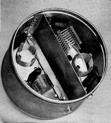
The two-band filter for coax lines; 80-meter filter at left, 40-meter filter at right. The coils in each filter are self-supporting and are oriented with their axes at right angles.
Usually you can consider yourself safe if you have an antenna coupler following the transmitter. The coupler provides enough selectivity to keep the harmonics from being radiated. However, many amateurs don't like to use a coupler because of the additional adjustments required when changing bands. There is another approach to the problem of harmonic attenuation, and that is the use of a filter installed in the coax feed line. The filter is a fixed device that doesn't require adjustment or tuning once it is constructed.
Half-wave filters
A "half-wave" filter is a special type which has the unique property that it doesn't have to be "matched," because whatever impedance may be connected to its output side will automatically be repeated at its input terminals. This means that such a filter can be inserted in the feed line without changing the load on the transmitter; except for the fact that it attenuates harmonics such a filter has no effect on the operation of the transmitter and antenna.
The half-wave filter is not critical of the standing-wave ratio on the line. A single design will work equally well with either 50 or 70 ohm coax and will tolerate mismatches of approximately 3 to 1. This limit is not due to any theoretical limitations in the filter itself, but is because of the limitations of the components used. With a large mismatch the currents or voltages in some parts of the filter may exceed safe values for the coils and capacitors.
The only drawback, and it is not a serious one, is that a separate filter is required for each band. This means the filter must be changed when a different band is used. However, this can be taken care of by installing phono-type plugs on the feed line and phono jacks on the filter. It is impracticable to use a switch to change filters because of the danger that harmonics will leak around the switch connections through stray capacitance and reach the antenna. It only takes a few seconds to change filters with the plug and jack system.
Making the filters
The assembly shown in the photograph consists of two half-wave filters, one for 80-meter operation and the other for 40. A coffee can makes an inexpensive container for the filters, and also offers excellent shielding. Both filters use the circuit given in Fig. 1.
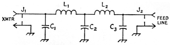
Fig. 1. Circuit of the half wave filter. A single set of circuit constants, as given below, will serve for one Novice bond, but different filters must be used on different bands.
| C1,C3 | 3.5 Mc: 820 pF mica, 500 volt. 7 Mc: 470 pF mica, 500 volt. 21 Mc: 100 pF mica, 500 volt. |
| C2 | 3.5 Mc: 1500 pF mica, 500 volt. 7 Mc: 1 nF mica, 500 volt. 21 Mc: 2 nF mica, 500 volt. |
| J1,J2 | Phono jacks. |
| L1,L2 | 3.5 Mc: 11 turns No. 20, 16 turns per inch, 1 inch diam. (B&W Miniductor 3015). 7 Mc: 8 turns No. 18, 8 turns per inch, 1 inch diam. (B&W Miniductor 3014). 21 Mc: 7 turns No. 18, 4 turns per inch, ½ inch diam. (B&W Miniductor 3001). |
The first step in building such a filter is to cut a shield from another tin can. The shield runs through the center of the coffee can and is soldered to the can at the sides and bottom. This separates the can into two shielded compartments.
Next, mount the phono jacks in place. These are installed approximately 1½ inches from the bottom of the can and about ¾ inch either side of the shield. The jacks can be installed by soldering them directly to the can, or else screws and nuts can be used.
The coils L1 and L2 are made from a single length of B & W Miniductor coil stock. See Fig. 1 for details on coil sizes. When cutting the coils from the original stock allow approximately 1M-inch lead length on each coil.
Note in the photograph how the coils are mounted at right angles to each other. This is done to minimize coupling between the coils. The ground leads to the mica capacitors are soldered directly to the can, and their other leads go to J1, J2 and the junction of L1L2, respectively. After assembly, replace the lid to complete the shielding.
Of course, if you plan to operate only on one band there is no need to make two filters. In such a case the internal shield can be omitted.
The half-wave filter attenuates all harmonics higher than its operating frequency and so is also useful in attenuating harmonics that could cause TVI. However, if you already have a TVI low-pass filter installed in your setup it can be left in place when the half-wave filters are used. Actually, there is no need to build a half-wave filter for 15-meter operation if you're already using a low-pass filter since the latter serves the same function.
Remember: Be sure to change filters when changing bands. If you don't you may blow out the mica capacitors.
Notes
- You should know this already from your Novice license examination, but it's worth repeating for emphasis.
Lewis G. McCoy, W1ICP.