A vacuum tube voltmeter r.f. probe
Measuring small r.f. voltages.
If you own a vacuum-tube voltmeter- a basic test instrument that is indispensable for anyone doing his own experimenting-and haven't equipped it with an r.f. probe it's probably just because of neglect, not cost. Even so, the probe described here is cheaper to make than any probe kit you can buy. It's a bare junk box that won't supply most, ij not all, of the parts.
A useful addition to the test gear of any ham who does experimenting is an r.f. probe. It has numerous applications, ranging from measuring oscillator injection voltage in a mixer stage to measurements on transmission lines. All r.f. probes have a common purpose - detecting and rectifying an a.c. voltage and delivering a proportional d.c. voltage to a vacuum-tube voltmeter. There are several types of rectifying probes, variously designed to read peak-to-peak, peak, or r.m.s. a.c. voltages at frequencies as high as 3000 Mc.
Either a vacuum-tube or crystal diode can be used as the rectifier. Vacuum-tube diodes can handle larger amplitudes of a.c. voltages than crystal diodes; and, in general, probes designed using vacuum-type diodes offer higher input impedance. However, the vacuum-tube probes have several drawbacks; they are relatively large and cumbersome, require heater and plate supplies, and usually have relatively high shunt capacitance. The use of a crystal diode instead of a vacuum tube simplifies probe construction, eliminates the need for a filament and plate supply, reduces shunt capacitance, and allows the finished probe to be more compact and lighter than would be possible using a vacuum-tube rectifier.
The probe shown in the photograph and schematically in Fig. 1 is of the peak-indicating, shunt type - so named because the diode is shunted across the circuit being measured - and uses a 1N34A germanium crystal diode rectifier.
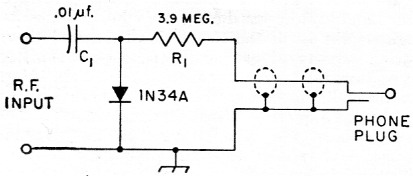
Fig. 1. The r.f. probe circuit.
Circuit operation
A probe of this type has definite limitations, and in order to appreciate them it is necessary to understand how the probe functions. The operation of the r.f. probe is analogous to that of an ordinary half-wave rectifier-filter combination, converting an a.c. input voltage to a pure d.c. output voltage. Referring to Fig. 2, assume that the a.c. input voltage is sinusoidal. Initially, when the voltage rises from zero and approaches its peak positive value (at point X) the diode conducts and the input capacitor C1 charges through the low forward resistance of the diode to approximately the peak voltage. When the input voltage decreases from its peak value toward zero, C1 begins to discharge through the series combination of R1 and R2, the latter being the vacuum-tube voltmeter's input resistance. C1 continues to discharge throughout the rest of the cycle, through 0 to Y in the negative direction and back to 0 again, but if the time constant(1) of the circuit is large compared with the time of one a.c. cycle the capacitor will lose only a small part of its charge. Thus when the input voltage again goes in the positive direction the diode is back biased, and cannot conduct until the amplitude of the input voltage exceeds the potential of the partially-discharged capacitor. In each succeeding cycle, as the input voltage nears its maximum positive value and overcomes the voltage stored in C1, the diode conducts and C1 again charges rapidly through the low forward resistance of the diode.
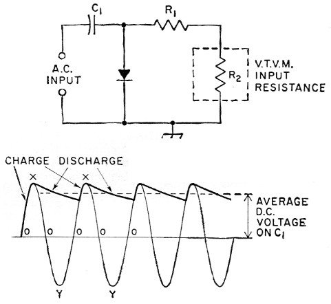
Fig. 2. How the probe operates.
Theoretically, R1 and R2 should be the only discharge path for C1; however, in the practical case - and particularly when crystal diodes and not vacuum tubes are employed - it is possible for C1 to discharge partly through the back resistance of the crystal diode. The back resistance is normally about 1000 times the forward resistance, but is generally small compared with the sum of R1 and R2. Thus the time constant of the circuit actually is determined principally by the crystal back resistance.
Realizing basically how the probe functions, it should be evident that at some low input frequency the applied voltage will not change rapidly enough to keep the input capacitor C1 charged to approximately the peak voltage over the whole cycle. In other words, C1 will have time to discharge more than it should, and the average d.c. voltage from the probe will be proportionally reduced. This will cause erroneous readings, limiting the usefulness of the probe at low frequencies. For satisfactory operation the time constant of the circuit (C1 times the back resistance of the diode) should be 25 to 100 times as long as the time of one cycle of the lowest desired a.c. input frequency, values toward the higher figure being preferable. The actual back resistance of the diode is dependent on the applied voltage, but an average figure of 150,000 ohms can be used for general calculation purposes. Thus, for the circuit shown in Fig. 1 the lowest usable frequency of the probe is approximately:
![]()
where f is the frequency in cycles per second and Rb is the crystal back resistance in megohms. Increasing the capacitance of C1 will extend the lower frequency limit of the probe.
The upper frequency limit for a probe of this type is approximately 250 Mc. The mechanical design and construction can markedly influence the performance of the probe in this respect. Long leads and wiring in which no attention is paid to stray capacitance will considerably reduce the over-all effectiveness of the probe at the higher frequencies. At high frequencies it is also essential to provide short, low-inductance r.f. connections to the test circuit. A flexible copper-braid grounding strap will provide a low-inductance return path. In general, at the upper frequencies the usefulness of the probe is limited mostly to detecting the presence of r.f. voltages and comparing relative amplitudes, rather than in making accurate quantitative voltage measurements.
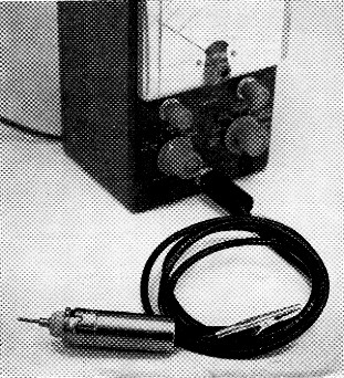
The r.f. probe is used in conjunction with a vacuum-tube voltmeter. The case of the probe shown here is constructed from a 7-pin ceramic tube socket and a 21%-inch tube shield. A half-inch grommet at the top of the tube shield prevents the output lead of the probe from chafing. The flexible copper-braid grounding lead and alligator clip provide a low-inductance return path from the test circuit. The d.c. output of the probe goes to the phone plug, which plugs into the d.c. input jack of the v.t.v.m.
The capacitor C1 charges to the peak amplitude of the applied voltage, as described earlier, but usually it is desired that the r.m.s. values of the voltage be indicated. To do this automatically, it is necessary to set up a resistance voltage divider to convert peak to r.m.s. The r.m.s. value of a sine wave is 0.707 times the peak, and therefore this ratio is used in the voltage divider, the resistance across which the d.c. voltage is measured being 0.707 times the total resistance; that is,
![]()
where the circuit is as shown in Fig. 2. The probe described here is designed to be used with any of the several "11-megohm" vacuum-tube voltmeters on the market (the actual input resistance of these meters is 10 megohms since the d.c. probe contains a 1-megohm isolating resistor). Solving the equation gives R1 = 0.414R2, and substituting 10 megohms for R2 yields 4.14 megohms for the value of R1. Keeping in mind that the average of the charge on-Cj is not quite equal to the peak of the input voltage, the actual value for R1 should be chosen slightly smaller than the calculated value. In this case a value of 3.9 megohms is not only sufficiently accurate but also allows the builder to use a standard resistance value.
Construction
The unit shown in the photograph and schematically in Fig. 1 is similar in circuitry to most of the conventional peak-indicating, shunt-type commercial r.f. probes. However, it can be constructed for considerably less than the cost of a commercial unit. If all parts, including the shielded wire (microphone cable or small coax), alligator clip, tie point, resistor, phone plug, tube socket, tube shield, capacitor, and diode are purchased new, the total cost of the unit is approximately $2.25. Utilizing junk-box parts can decrease the total cost substantially.
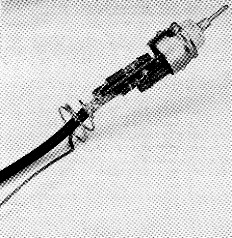
Close-up of the inside of the probe. The 1N34A crystal diode rectifier, calibrating resistor, and input capacitor are mounted tight to the terminal strip with shortest leads possible. Spaghetti tubing is placed on the diode leads to prevent accidental short circuits. The tube-shield spring and flexible-copper grounding lead are soldered to the cable braid (the cable is RG-58/U coax in this probe). The tip can be either a phone tip or a short pointed piece of heavy wire.
The isolation capacitor, crystal diode, and resistor are mounted on a bakelite 5-lug terminal strip, as shown in the sketch. One end lug should be rotated 90 degrees so that it extends off the end of the strip. All other lugs should be cut off flush with the edge of the strip. Cut off about an inch of the outer insulation of the cable, unravel the braid three-quarters of an inch, slip a piece of spaghetti over the free end of the braid, and then solder its end to the ground lug on the terminal strip, as shown in Fig. 3. Remove the spring from the tube shield, slide it over the cable, and crimp it to the remaining quarter inch of shield braid. Solder both the spring and a 12-inch length of flexible copper braid to the cable shield.
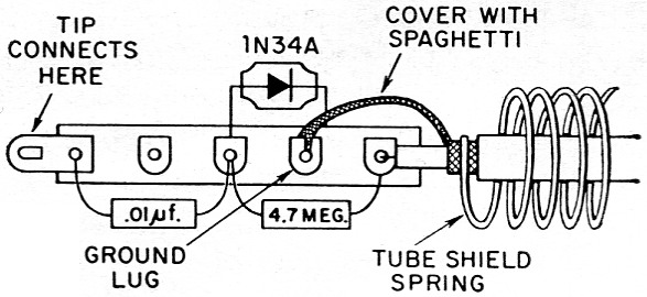
Fig. 3. Component mounting details.
Next, cut off the pins on a seven-pin miniature ceramic or mica shield-base tube socket. Be sure to use a socket with a cylindrical center post, such as the Johnson 120-277. Crimp the terminal lug previously bent out at the end of the strip and insert it into the center post of the tube socket from the top. Insert the end of a phone tip or a pointed piece of heavy wire into the bottom of the tube socket center post, and solder the lug and tip to the center post. Insert a half-inch grommet at the top of the tube shield, and slide the shield over the cable and flexible braid down onto the tube socket. The spring should make good contact with the tube shield to insure that the tube shield (probe case) is connected to the grounded side of the circuit. Finally, solder an alligator clip to the other end of the flexible braid and mount a phone plug on the free end of the shielded wire.
Be sure to mount components close to the terminal strip, as this keeps lead lengths as short as possible and minimizes stray capacitance. Use spaghetti over all wires to prevent accidental shorts. When soldering the crystal diode, hold the end to be soldered with a pair of long-nose pliers; this helps conduct damaging heat away from the diode.
Using the probe
The a.c. input voltage that the probe can handle safely is limited to about 21 volt r.m.s. or 30 volt peak, as a result of the 60 volt peak-inverse rating of the 1N34A crystal diode. The phone plug on the probe cable plugs into the d.c. input jack of the v.t.v.m., and r.m.s. voltages are read on the vacuum-tube voltmeter's negative d.c. scale. When using the probe be sure that any d.c. voltage on the circuit being checked does not exceed the d.c. voltage rating of C1 (600 volt for small ceramic capacitors).
The accuracy of the probe is approximately ±10 per cent from 50 kc to 250 Mc. For example, if the error of the v.t.v.m. used with the probe is ± 5 per cent, then the over-all error of the measuring system is ± 15 per cent. At low values of input voltage, below a volt or so, the accuracy of the probe is somewhat poorer because of the nonlinearity of the 1N34A crystal diode. At these lower input voltages the output of the probe more closely approaches a square-law relationship than a linear one.
The approximate input impedance of a probe of this type is 6000 ohm shunted by 1.75 pF (at 200 Mc),(2) and the amount of error introduced because of circuit loading by the probe is dependent on the impedance of the source of the a.c. voltage being measured. If peak values are desired rather than r.m.s., the r.m.s. values can be multiplied by 1.41 or the peak scales on the v.t.v.m. can be read directly if so calibrated.
Notes
- See The Radio Amateur's Handbook, chapter on circuit fundamentals. The time it takes for a capacitor to lose 63.2 per cent of its initial potential is defined as the time constant. The time constant in seconds is equal to the product of the capacitance in µF by the resistance in megohm. The smaller the RC product the less time it takes for the capacitor to discharge.
- Ghiradi and Middleton, How to use test probes, published by John F. Rider Publisher, Inc., 116 West 14th St., New York 11, N. Y.
Kenneth C. Lamson. W1ZIF.