Simple converter unit with 24 Mc output using the 80 meter v.f.o. on 2
The little unit described here by W2BLO is the missing link that will tie your 80 meter v.f.o. to your rockbound 144 Mc. It requires only one or two surplus crystals.
There are undoubtedly numerous hams operating on 144 Mc using the conventional exciter lineup consisting of an 8 Mc crystal, 12AT7 third-overtone crystal oscillator-tripler, and 5763 doubler, or the like. Many of these same hams have reasonably stable basic v.f.o.'s on 3.5 Mc which they use on the so-called "d.c." bands. The presence of this latter unit, with the advantages of v.f.o. operation, which are apparent even on 144 Mc, and the simplicity and low cost of putting it to use with the little unit described herewith, make it unnecessary to be without such a useful adjunct.
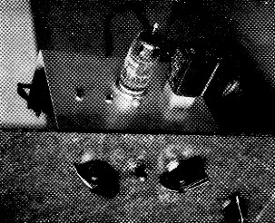
The unit mounted on the front panel of the 2 meter rig at W2BLO. The crystals plug into a dual crystal socket.
At this writing, the author has just finished a year and a half of 144 Mc operation with the aforementioned conventional crystal-controlled lineup. He has considered himself fortunate to be able to jump about the band rather freely with a bank of six crystals and a switching arrangement with an equal number of settings, to say nothing of a few spare rocks which could be substituted in one of the receptacles if desired. There were times, however, when contacts were missed, or during contests and band openings, when the 80-meter exciter with its v.f.o. got more than a casual glance. Although the v.f.o. stability was such that we might have considered a simple multiplier to put it to use, its tuning range barely covered the 3.5-4 Mc band, and therefore its harmonics would not hit the 114 Mc. band. Thus, its real possibilities did not occur to us for many months.
The solution
Then, a few weeks ago, our friend Fred Winters, W2PZF, was visiting in our shack when the conversation hit upon the subject of the v.f.o. and how nice it would be to use it on 144. At his suggestion, we got out paper and pencils and a crystal catalog (Texas Crystals) and began to make calculations based on a heterodyne system. We finally hit upon two low-cost surplus crystals which would give us what we needed to cover the 144 Mc band. When operated in a third-overtone oscillator circuit, stock crystals of 6825 kc and 6900 kc oscillate on 20.475 Mc and 20.7 Mc, respectively. When mixed with the 3.5-4 Mc signal from the v.f.o. unit, these signals add up to the 24 Mc frequencies desired.
Using the capacitive feedback type of overtone oscillator in our 144-Mc. rig, and crystal switching, as we do, we were able to devise a simple method of switching the mixer output into one of the crystal sockets and at the same time provide for neutralization of the former crystal oscillator. The latter is a necessity because the oscillator operates as a straight-through amplifier on 24 Mc. (see Fig. 1). With the crystal switch in the other position (or, actually, in one of five other positions in our case), the stage is still used as a crystal oscillator when desired.
The converter
The mixer-oscillator is of conventional design, utilizing a 12AT7. The oscillator is a capacitive-feedback overtone type and requires a single-pole double-throw rotary switch for switching the two crystals. A TV width control proved to be a convenient unit for the 3.5 Mc slug-tuned circuit. We removed turns down to one close-wound layer and shunted it with a 50 pF ceramic fixed capacitor. The coupling to be used between this coil and the v.f.o. link depends upon the output power of the v.f.o. We had to couple ours very loosely because our v.f.o. exciter unit has a 6L6 doubler for the output stage, which can easily overdrive the mixer grid.
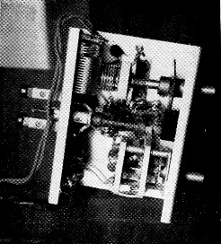
A bottom view of the mixer-oscillator unit. The modified TV width control, used for the 80 meter tuned circuit, is in the center, foreground, while the slug-tuned oscillator coil can be seen just behind it. The link from the v.f.o. unit is connected to the binding posts at the left. At the top is the 24 Mc tuned circuit and link, while the crystal switch is at the bottom. A toggle switch is in series with the B-plus lead so that the unit may be switched off separately if it is desired to operate the rig crystal-controlled.
The entire unit was constructed on a 4½ × 3¼ × 2 inch aluminum chassis. Power to operate it is taken from the main rig through a three-wire cable. A toggle switch in the B-plus lead provides for switching the mixer-oscillator off when the rig is crystal-controlled.
Other systems
Admittedly, the heterodyne method could be utilized to give a mixer output frequency of 8 or 12 Mc. and would require only one crystal to cover the entire band. This would have the additional advantage that its output could be fed as a crystal substitute into the oscillator, which would then act as a tripler or doubler and would require no neutralization. However, we preferred the 24-Mc. arrangement, not only on the theory that there would be less likelihood of TVI, but also because it results in a drift ratio between the v.f.o. and the 144-Mc. band of 1 to 6, as compared to 1 to 18 or 1 to 12 with the other systems.(1)
Of course, the 6825 kc crystal alone would be sufficient for anyone who has no reason to operate above 146.85 Mc However, we not only one, ate in a RACES net on 147.24 Mc, but also like to use the upper portion of the band for local ragchews. The 6900 kc crystal gives a big overlap and covers the rest of the band very nicely.
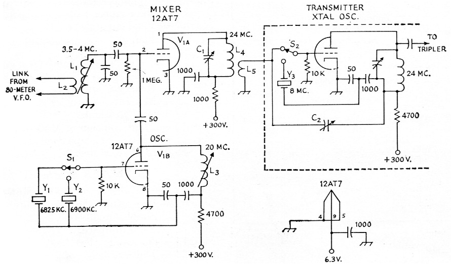
Fig. 1. Conversion circuit for obtaining 24 Mc output with 3.5 Mc input. Capacitances are in pF. Bypass capacitors are disk ceramic; other fixed capacitors should be NP0 ceramic or mica. Resistors are ½ watt and resistances are in ohms.
| C1 | 25 pF miniature variable (Bud LC1-642 or equivalent). |
| C2 | 30 pF mica trimmer. |
| L1 | 50 turns No. 26 enam., on ¼ inch iron slug form (Stancor. WC-1 TV width control with turns removed leaving single layer, full length, approx. 40 µH). |
| L2 | Single turn of hookup wire loosely coupled to ground end of L1. |
| L3 | 12 turns No. 32, 3/16 inch long on 3/8 inch iron slug form, approx. 5 µH. |
| L4 | 15 turns No. 20, ¼ inch diam. 1 inch long (B & W 3007 Miniductor, approx. 1.8 µH). |
| L5 | 2. or 3 turn link at ground end of L4 (same coil stock as for L4 may be used). |
| S1,S2 | S.p.d.t. rotary. |
| Y1,Y2,Y3 | See text. |
Calibration
Since the third overtone of a crystal will not necessarily be an exact multiple of the fundamental frequency, it is important to check the oscillator frequency in the 20 Mc range, or the mixer output frequency in the 24 Mc range, before setting up a 144 Mc calibration chart based on the v.f.o. calibration. If a frequency meter for these frequencies is not available, checks may be made against known frequencies in the 144 Mc band, making sure that you are listening to the right signal, since harmonics of various frequencies resulting from the mixing process are likely to be heard, almost as loud as the fundamental, in the receiver.
Once the oscillator frequency is known and the calibration definitely established, a 144 Mc calibration chart may be drawn up, and it is suggested that this include receiver settings. At W2BLO we show the frequency and the v.f.o. dial setting for each dial division on the receiver. This is handy and almost necessary if one wishes to be able to "zero in" quickly to a particular spot on the receiver dial, since the harmonics mentioned in the paragraph above can cause some confusion if one tries to do it entirely by ear.
Spurious output
One disadvantage of the heterodyne method of frequency conversion is that spurious frequencies are generated which may get through to the final amplifier or antenna. Recognizing this fact, several checks were made both with a g.d.o. and with the assistance of local amateurs with sensitive receiving systems. All checks showed that. spurious signals were negligible so long as the coupling between the v.f.o. and the 80 meter coil in the mixer was adjusted to the minimum required for adequate drive.
Notes
- All heterodyne systems produce spurious beats, some of which may reach the transmitter output at substantial level. The output of any transmitter using such a system should be checked carefully as mentioned later in the article. - Ed.
Elwin A. Guest, W2BLO.