"Der Loudenboomer" High-power grounded-grid AB1 linear for multiband s.s.b.
This grounded-grid linear with built-in filament, bias and screen supplies is capable of handling maximum legal s.s.b. input. Of more than ordinary interest are the control and protective circuits which make the amplifier virtually blow-up proof.
What price high power? Well, actually not too much when it is made a community project.
A few months ago, WORPE suggested that the spare-time manufacturing facilities of Radio Industries, Inc., and the procurement facilities of several of the local hams be united for the purpose of constructing a group of s.s.b. linear amplifiers at nominal cost to each of the participants. A quick meeting of W0UI, W0AIW, W0HRG, W0LVA, W0MMB, W0RPE and W0UQV was called and thus "Der Louden-boomer" project was born.
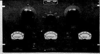
The panel is 10½ inch high and of standard 19 inch rack width. The pi-network coil switch is between the tank-capacitor and loading-capacitor controls. Across the lower portion of the panel, from left to right, are screen meter, a.c. power switch, grid meter, S5 (above) and S3, and the cathode-current meter.
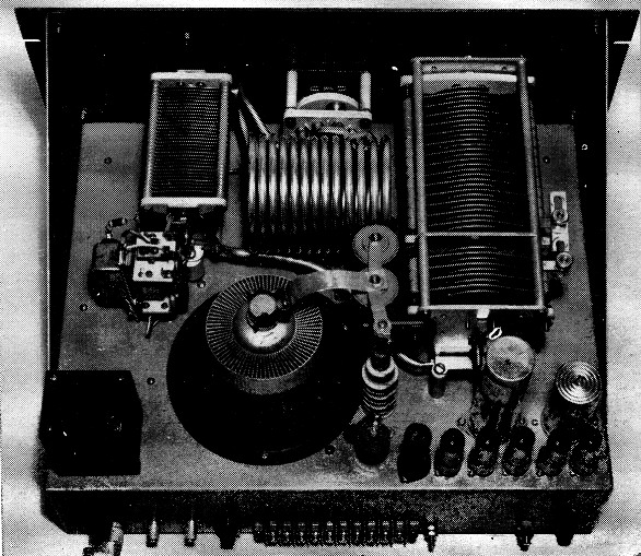
A standard 17 × 13 × 4 inch chassis provides adequate space for the amplifier. The antenna relay is to the rear of the pi-network loading capacitor at the left. Behind the dual tank capacitor at the right are filter capacitors, voltage-regulator tubes and the thermal time-delay switch. The screen-supply filter choke is in the rear left-hand corner. The strap (Si) which connects the two stators of the tank capacitor for operation on the lower frequencies may be seen at the right of the capacitor.
Several evenings were spent. kicking ideas around. The good ones were sifted out and these, together with some unique features from current commercial s.s.b. transmitters, finally froze the design. The schematic gradually took form, and the fabrication of seven sets of parts was under way. Evening operation of punch presses, lathes and welding equipment by the seven pencil jockeys was successfully concluded with loss of neither hand nor limb.
The story of these amplifiers is written not so much with the idea that they will be closely duplicated, but more with the hope that they will furnish some suggestions that may be combined with the individual imagination in the design of any high-power AB1 linear. To each his own, since no two hams have the same requirements or desires.
R.F. circuit
Basically, the amplifier was designed around the Eimac 4CX1000A tube, and was to be driven by any of the 100-watt s.s.b. exciters currently available. To make the most efficient use of these exciters, a grounded-grid circuit configuration was indicated.
The complete circuit diagram is shown in four sections for the sake of clarity. Fig. 1 shows the r.f. circuit. It is a quite conventional arrangement for grounded-grid operation and has a pi-network output circuit covering all bands from 3.5 to 28 Mc. with a tapped coil. The tank capacitor is a special dual unit made by Johnson. One section has a maximum capacitance of 50 pF while the maximum of the other section is 300 pF. The 50 pF section alone is used for 14, 21 and 28 Mc. A strap connects the 300 pF unit in parallel for the two lower-frequency bands. This arrangement reduces the tank-capacitor minimum on the higher-frequency bands where stray capacitances make it difficult to hold the tank Q down to a reasonable value. A single-section vacuum variable could be used instead of the dual unit, since capacitors of this type have low minimums. On 80 meters, the output capacitance is brought up to the required value by switching in a 1500 pF fixed capacitor in parallel with the variable loading capacitor C12.
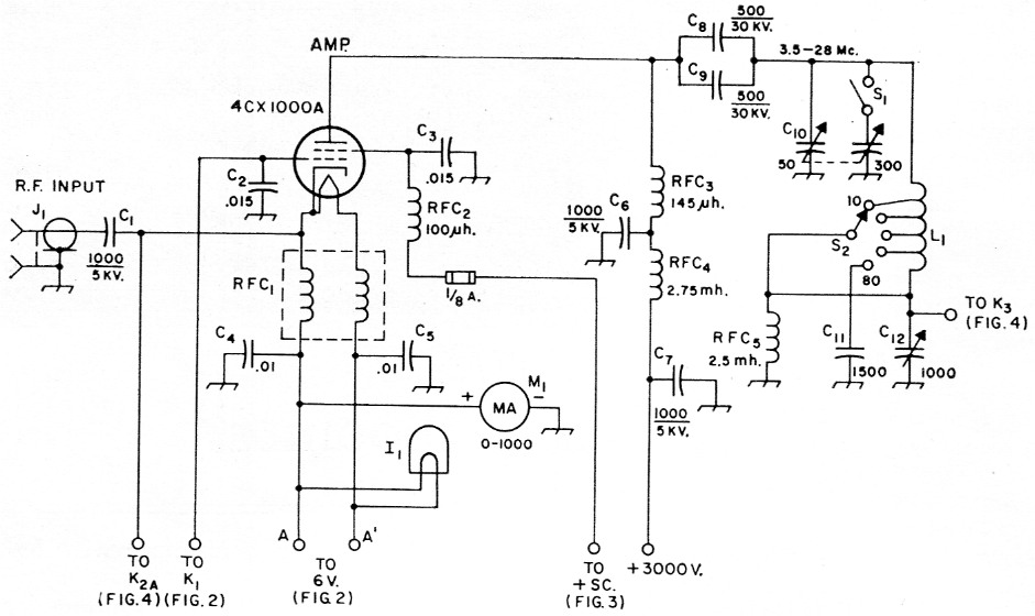
Fig. 1. Circuit of the 4CX1000A grounded-grid amplifier. Capacitances less than .01 µF, are in pF.
| C1,C6,C7 | Ceramic (CBI 858S-1000). |
| C2,C3 | Three 5000 pF 600 volt disk ceramics in parallel. |
| C4,C5 | 500 volt mica. |
| C8,C9 | Ceramic TV capacitor. |
| C10 | Special dual capacitor; see text. |
| C11 | Three 500 pF 10 kV "Glassmike" capacitors in parallel (Condenser Products LSG501-1 OM). |
| C12 | 1000 pF 2 kV variable (Johnson 1000E20). |
| I1 | 6 volt dial lamp. |
| J1 | Chassis-mounting coaxial receptacle (UG-290 /U). |
| L1 | 13 turns ¼ inch copper tubing 5 inches long, 3 inches in diameter, tapped at approximately 6 turns, 4 turns, 3 turns and 2 turns. (Adjust to resonate with C10 set at 330, 150, 70, 40 and 25 pF respectively for the bands 3.5 through 28 Mc.) |
| M1 | 2½ inch d.c. milliammeter (Marion). |
| RFC1 | Bifilar filament choke (B & W FC-15). |
| RFC2 | 125 mA r.f. choke (Miller 4642). |
| RFC3 | Plate r.f. choke (National R.175-A). |
| RFC4 | 1 A r.f. choke (Miller 7868). |
| RFC5 | 125 mA r.f. choke. |
| S1 | Strap connector on C10 (see top-view photograph). |
| S2 | Heavy-duty 25 A ceramic single-pole 5-position rotary (surplus). |
The bifilar choke RFC1 provides the necessary r.f. isolation between filament and ground. The milliammeter M1 reads cathode current. The screen is protected by a 125 mA fuse.
Bias supply
Fig. 2 shows the bias supply. For the sake of compactness, semiconductors are used as rectifiers in a full-wave bridge configuration. An 0B2 provides a constant-voltage source across which a voltage divider permits adjustment of bias to give the desired idling plate current. The transformer is a special job which includes a filament winding for the 4CX1000A. If space permits, individual transformers may be substituted, of course.
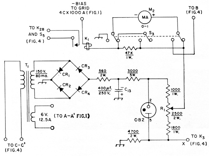
Fig. 2. Bias supply for the grounded-grid amplifier. K1 is a safety device which trips if grid current flows. The milliammeter may be switched by S3 to read amplifier r.f. output voltage.
| C13 | Two 200 µF, electrolytic units in parallel. |
| CR1,CR2,CR3,CR4 | Silicon diode (1N540 Texas Instruments). |
| K1 | 5000 ohm 5 mW sensitive relay (Sigma type 5F-400S). |
| M2 | 2½ inch d.c. milliammeter (Marion). |
| R1 | Bias-control potentiometer. |
| S3 | Three pole double throw rotary, lever or push-button type with spring return to normal position shown (CRL 1457). |
| T1 | Power transformer: 150 V, 80 mA; 6 V 12.5 A (Special). Individual transformers may be substituted. |
The 4CX1000A has a grid dissipation rating of zero watts, so any flow of grid current must be guarded against. This function is performed by K1 which will trip at a grid current of 3 mA. Operation of this relay serves to trip relay K2 in Fig. 4 which, in turn, cuts off plate and screen voltages and shorts r.f. drive to the amplifier. The meter M2 serves only as an indicator for adjustment of drive just below the grid-current point. S3 has a spring return which holds the switch in the normal position shown. The momentary-contact position shifts the meter to read rectified r.f. voltage at the output of the amplifier while it is being adjusted for maximum output.
Screen supply
A regulated screen supply is shown in Fig. 3. Here again semiconductors are used to conserve space. The four series-parallel connected 0A2 regulators will handle a variation of 50 mA or more. However, analysis of the screen-current pulse indicates that the ratio of maximum instantaneous current to the d.c. value is approximately 5 to 1, which means a peak screen current of about 250 ma. Regulation at these peaks is provided by the storage capability of the 40 µF output capacitor in the supply filter. The combination of resistor network between the pairs of VR tubes and the tap back to supply voltage is a measure that will assure reliable parallel operation.
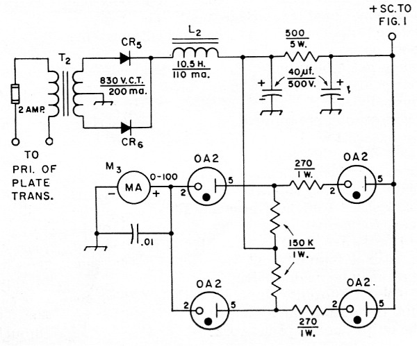
Fig. 3. Regulated screen supply for the "Loudenboomer."
| CR5,CR6 | Each has four 1N540 (Texas Instruments) silicon diodes in series. |
| L2 | Filter choke (Stancor C1001). |
| M3 | 2½ inch d.c. milliammeter (Marion). |
| T2 | 830 volt, c.t., 200 mA (Stancor PC-8301). |
| Electrolytic capacitors are each two 20 µF units in parallel. | |
To keep the screen-current meter at ground potential, it is connected in series with the regulator tubes, rather than in the positive d.c. lead to the screen. In this position it indicates VR-tube current rather than actual screen current. With the amplifier in the stand-by condition, the meter reads about 60 mA. When the amplifier is driven, screen current is indicated by excursions of the meter pointer toward zero. If the reading falls to zero, it indicates that regulation is lost and that the screen current is above normal.
The primary of T2 is connected in parallel with the primary of the plate transformer so as to be controlled simultaneously with it.
Control and protective circuits
Fig. 4 shows the control and protective-circuit wiring. All power is controlled primarily by S7, which also controls operation of the tube-cooling blower B1. However, filament and bias voltages will not be applied until Ss closes. This switch is operated by a paddle inserted in the air stream of the blower to assure that filament and bias voltages will not be applied without the blower in operation. One of the quickest ways to damage the 4CX1000A is to apply plate and screen voltages before the cathode has reached normal operating temperature. For this reason, the control circuit is so arranged that plate and screen voltages cannot be applied until after the 3-minute time-delay switch S4 has closed.
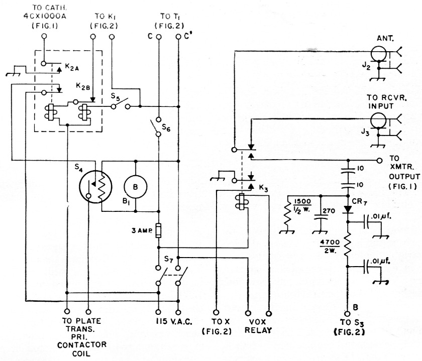
Fig. 4. Control and protective circuits of the 4CX1000A amplifier. Capacitors of 0.01 µF are disk ceramic; others are stable ceramic or mica. Capacitances are in pF unless indicated otherwise. Resistances are in ohm.
| B1 | Blower (W. W. Grainger 2CD67). |
| CR7 | 1N34 crystal diode. |
| J2,J3 | Chassis-mounting coaxial receptacle (SO-239). |
| K2 | Electrical-reset locking relay, 115 V a.c. coils, d.p.d.t. contacts each section (Guardian 1R-1200-1200-11.5GG). See text for explanation. |
| K3 | Antenna change-over relay (Leach 1177CBF). |
| S4 | Thermal delay switch (GV Controls Inc. R-F160). |
| S5 | Push-button switch, normally open. |
| S6 | S.p.s.t. normally open switch with paddle attached to operate from blower air stream (Acro TD-48l or similar). |
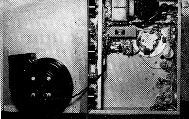
In mounting components on the under side of the chassis, space is provided for the blower attached to the bottom cover. The filament choke and protective relays K1 and K2 are to the left of the tube socket. The two power transformers are at the top in this view. A baffle strip shields the meters.
From this point on, control is through the VOX relay contacts which actuate the changeover relay K3. In the normal position of K3, the antenna is connected to the receiver and the auxiliary contacts are open. The grid bias under this condition is approximately 100 volts, which reduces the screen and plate currents to low values on stand-by. When K3 is actuated by the VOX relay, point X in Fig. 2 is grounded through the auxiliary contacts of K3, which brings the biasing voltage to the normal operating value of -60 when R1 (Fig. 2) is properly adjusted.
K2 is a locking relay with mechanical latching and electrical reset. On Ken, one normally-closed contact and one normally-open contact of the d.p.d.t. complement are used. On Kee, only one normally-closed contact is used. The relay is latched mechanically in the normal operating position shown in Fig. 4, neither coil being energized. The primary circuits of the plate and screen transformers are held closed through the normally-closed contact of S2A. When a grid overload occurs (approximately 3 mA), K1 (Fig. 2) closes, thereby energizing K2A. K2 is now latched in the opposite position. This action performs three functions: excitation is shorted, plate and screen voltages are removed and Ken is deenergized (but held mechanically). K2 can be reset to normal position by closing the pushbutton switch S5. The relay should be mounted in such a position that the excitation-shorting leads may be made short.
The r.f. output voltmeter rectifier CRS operates from a tap on a capacitive divider across the output of the pi network.
Essential constructional details are covered by the photographs and their captions. Some advance thought should be devoted to the distribution of components on the under side of the chassis so as to leave adequate space for the blower. C2 and C3 each consist of three units in parallel, one unit in each case being connected to one of the three "ears" on the fin terminals. The open-type antenna relay is mounted directly at the output terminals of the pi network so as not to introduce any change in s.w.r. on any part of the line. The r.f. voltmeter diode and associated components are mounted in a shielding box alongside the relay.
Adjustment
Fifty watts will drive the tube to the point of grid-current flow. The average cathode driving impedance is in the order of 40 ohms. But this does not mean that a 50 ohm coaxial cable will automatically be properly terminated by the amplifier. The impedance varies widely with excitation and loading. For this reason, keep the ca-able connection to the driver as short as possible.
A grounded-grid Class AB1 linear must be adjusted somewhat differently than the usual Class C amplifier and with the 4CX1000A special care must be exercised to prevent exceeding the control-grid and screen-grid dissipation ratings. The reader is referred to the single-sideband chapter of the ARRL Handbook, 1960 edition, for information on checking the operation of linear amplifiers. The bias should be adjusted for an idling current of 200 to 250 mA. The drive should be maintained at a level just below the grid-current point. Under some operating conditions, a small reverse grid current may be indicated. This is a result of secondary emission but it is of no consequence since it does not impair the operation of the tube.
The simplest way to arrive at proper loading is to set up on single-tone (c.w.) and resonate the plate tank by tuning for a peak in screen current, and then loading for a screen-meter reading of approximately 30 mA. Approximate output-capacitor values for a 50 ohm load are 2000, 1000, 500, 330 and 250 pF for the respective bands 80 through 10 meters.
"Der Loudenboomer" has turned out to be a real flame thrower. It has operated smoothly without the need for any form of parasitic suppression. At least part of the credit for this should go to the excellence of tube design, although the short, heavy leads in the r.f. plate-to-cathode path also contribute to the stability at v.h.f. Based on the ratio of r.f. power output ta d.c. power input to the final amplifier, the efficiency is better than 70 per cent. The total r.f. output includes, of course, a good share of the driver output.
Lee Bergren, WOAIW
W.T. Bishop, W1UI.