Low-frequency mobile
A Low power transmitter-receiver for 160 or 80 meter.
Mobile operators who are tired of trying to buck the nighttime QRM on 75 may find relief in going to 160. Not only is the theoretical ground-wave coverage better on the lower frequency band, but the power-level restriction in force at the present time also makes competition less severe. For those who prefer it, the unit is easily adapted to 75.

The authors have managed to find space in G3KEP's three-wheeled Frisky Sport not only for themselves but for the gear described in the article.
The modern trend in mobile equipment seems to be toward the separate transmitter and receiver or converter arrangement. While this in itself is quite satisfactory in other respects, it does not result in maximum conservation of space - a vital consideration where the average small European car is concerned. For this reason, it was decided to make the receiver, modulator and transmitter in a single cabinet, with a vibrator power supply in the trunk. The complete unit is assembled on a 10 × 7 × 2¼ inch chassis which fits into a 11 × 8 × 7 inch cabinet. (Closest U.S. sizes are 10 by 8 by 2½ inch, and 14½ by 8 by 8¼ inches.)
Because of the limited battery capacity, low power was essential. On 160 meters the maximum input power permitted in the United Kingdom is 10 watts. Therefore, this band was chosen because of the proportionately low competitive QRM level. Coil dimensions for the 75-meter band will also be included for those who prefer this band.
Transmitter
The transmitter is primarily crystal controlled, although provision is made for feeding in an 1 external v.f.o. The oscillator comprises a 6BA6 in a Pierce circuit. Six crystals are provided, the desired one being selected by means of a seven-position, two-pole rotary switch, S1. The seventh position is taken to a coaxial socket, Js, at the rear of the chassis for connection to an external v.f.o. if this is desired. The power amplifier is a 5763. The pi-network output coupling is designed to feed directly into the whip antenna. Because of the comparatively low power involved, ordinary broadcast-type variable capacitors are adequate in the output circuit.
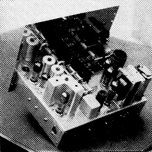
In this view, the receiver section is on the left and transmitter on the right, with the audio section at the rear of the chassis. A row of crystals occupies the central area.
Modulator
Heising modulation of the plate and screen of the 5763 is effected by means of an audio section common to transmitter and receiver. The modulation inductor L4 may be any small choke having an inductance of about 10 henrys with a d.c. rating of 80 mA. A carbon breast microphone is used because of the lower amount of acoustical background noise associated with this type of microphone. Two spring clips under the chassis retain the 3 volt energizing battery for the microphone, and this is made accessible without removal of the rig from the car through an opening in the bottom of the cabinet. The battery is connected via the change-over relay to the chassis. No audio gain control is provided as this was thought unnecessary and the modulation level is preadjusted by means of the potential divider R3 and R4. The total value of the potential divider should be about 500 k, and the individual resistor values should be predetermined by experiment.
Receiver
To obtain good selectivity, and the high sensi- tivity advantageous in mobile work, a superhet design is employed. This is of conventional circuitry and consists of a 6BA6 r.f. amplifier, 6AU8A mixer-oscillator, 6BA6 i.f. amplifier and 1N34A germanium crystal diode detector. The r.f. and oscillator coils are British Denco noval-based plug-in coils, but these, of course, may be replaced by any other suitable types. A three-gang 100 pF variable capacitor C3 is used with sufficient padding to spread the 1.8 Mc band over the whole of the capacitance swing. The i.f. transformers T1 and T2 are ordinary 465 kc broadcast receiving types. A variable resistor in the cathode of the i.f. amplifier stage is used as an i.f. gain control. When this control is turned fully clockwise (toward ground), oscillation of the stage occurs, so providing facility for c.w. reception.
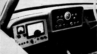
The 160 meter mobile unit installed in the compact car of one of the authors. Below the meter are the controls for the pi network-tuning capacitor, left, and loading capacitor, right. Along the bottom of the panel, from left to right, are the send-receive switch Sa, the + B switch Sa, the c.w./phone switch Sz, key i jack, crystal switch Si, two microphone jacks (one for each operator), headphone jack, a.f. gain control and regeneration control R1.
The degree of regeneration is predetermined by varying the input-to-output capacitance of the 6BA6. This is done by connecting a small length of insulated wire to the plate pin and bending it toward the control-grid wiring (C9).
The output from the i.f. amplifier is fed to the semiconductor diode detector, and thence via the change-over relay to the audio section. An a.f. gain control is provided at the output of the detector. The headphone jack is so wired that the loudspeaker is disconnected upon insertion of the plug of the high-impedance headphones.
Change-over switching
Transmit-receive switching is done by means of a six-pole changeover relay.(1) This is operated from the heater supply and may be switched by either of two toggle switches - the first on the chassis itself (S4), and the other on the dash for easy accessibility. In the receiving position (shown in Fig. 1), Pole 1 of K4 (with S3 closed) connects plate voltage to the receiver, and Pole 2 connects plate voltage to the audio section. Pole 3 connects the input of the audio amplifier to the detector output. Pole 4 connects the output of the audio section to the headphones and speaker transformer T4. Pole 5 connects the antenna to the receiver input. Pole 6 is shorted to ground.
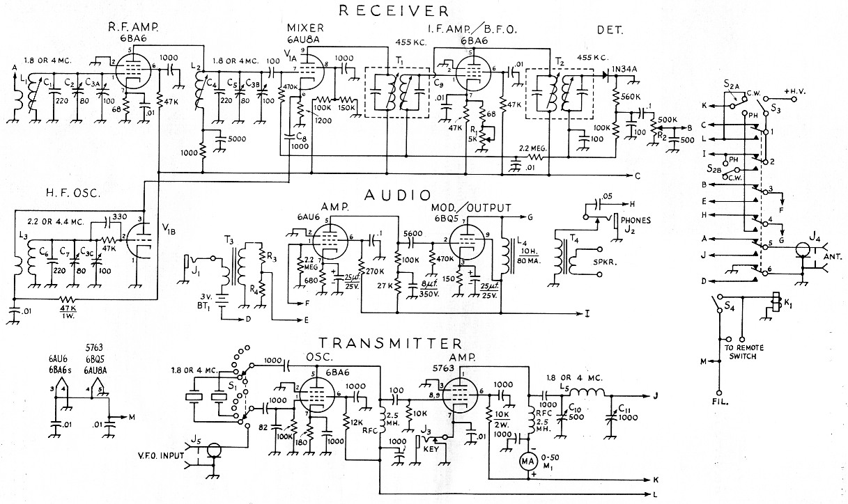
Fig. 1. Circuit diagram of the low-frequency mobile transmitter-receiver. Resistances ore in ohms, and resistors are ½ watt unless otherwise indicated. Disk ceramics are recommended for fixed capacitors having values from 1 nF to 10 nF. Fixed capacitors of smaller values, not listed below, should be mica or stable ceramic; larger values should be paper, except for capacitors marked with polarity which are electrolytic.
| BT1 | 3 volt A battery, or flashlight cells. |
| C1,C4,C6 | Silver mica. |
| C2,C5,C7 | Mica trimmer. |
| C3 | Triple-gang 100 pF variable (Bud MC-888). |
| C8 | 1 nF mica. |
| C9 | See text. |
| C10 | Midget superhet variable, broadcast replacement type, sections in parallel (Allied 61 H 008). |
| C11 | Dual t.r.f. variable, broadcast-replacement type, sections in parallel (Allied 61 H 059). |
| J1 | Open-circuit jack. |
| J2,J3 | Closed-circuit jack. |
| J4,J5 | Chassis-mounting coaxial receptacle (SO-239). |
| K1 | 6 volt d.c. six-pole double-throw relay (see text). |
| L1,L2 | 1.8 Mc Approx. 23 µH on iron-slug form (Miller 21 A225RB1). Antenna coil 28 turns No. 28 at ground end of L1. 4 Mc Approx. 6 µH on iron-slug form (Miller 21 A686RB1). Antenna coil 5 turns No. 28 at ground end of L1. |
| L3 | 1.8 Mc Approx. 15 µH on iron-slug form (Miller 21 Al 55RB1). Tickler 20 turns No. 28 at ground end of L3 |
| L4 | Filter choke (see text). |
| L5 | 1.8 Mc Approx. 54 µH - 80 turns No. 24, 1 inch diam., 2½ inch long (B & W 3016 or Airdux 832T). 4 Mc Approx. 27 µH - 40 turns 1¼ inch long, same as above. |
| M1 | 50 mA d.c. meter. |
| R1 | Linear potentiometer. |
| R2 | Audio-taper potentiometer. |
| R3,R4 | See text. |
| S1 | Two-section 1 1-position rotary switch, 7 positions used (Centralab PA-2005). |
| S2 | D.p.d.t. toggle switch. |
| S3,S4 | S.p.s.t. toggle switch. |
| T1 | Standard or miniature 455 kc permeability-tuned i.f. transformer, input (Miller 1 2-C1). |
| T2 | Same as T1, but for output (Miller 1 2-C2). |
| T3 | Carbon-microphone transformer. |
| T4 | Universal speaker output transformer, 4500 ohm primary, 8 watt (Stancor A3825). |
With K1 energized through S4 (or the remote switch), Pole 1 connects plate voltage to the transmitter oscillator and to S2A. S2A connects the plate-supply input terminal of the final amplifier to the supply either directly for c.w. operation, or via Pole 4 and L4 for phone. Pole 2 applies plate voltage to S2B which is open in the c.w. position but which applies plate voltage to the modulator in the phone position. Pole 3 connects the microphone transformer T3 to the input of the audio section. Pole 4 connects the modulator output circuit to the r.f. amplifier when S2 is in the phone position as mentioned above. Pole 5 transfers the antenna to the receiver, and Pole 6 closes the microphone circuit.
The unit requires 300 volt at about 90 mA, and 6 volt at 3 A. The antenna is a loaded 12 ft whip mounted at the rear. The car, incidentally is only a bit over 9 ft. long!
Notes
David Noble, G3MAW
David M. Pratt, G3KEP.