I.F. noise limiter
Shunt peak clipper with automatic control and adjustable threshold.
Receiver noise-limiter development appears to have moved contrary to the flow of the art since the original work of Lamb.(1) While the pattern for over-all receiver circuit development has followed the path of continually increasing complexity, noise-limiter development has, essentially, taken the direction of simplification. This has necessitated compromises which have been justified by the fact that even the best and most complicated receiver noise limiters could be considered only relatively satisfactory.
Ideally, a noise limiter should operate at the antenna input in order to prevent overloading of any of the receiver circuitry. Such a location for the noise-limiting circuit is currently impractical, primarily because insufficient impulse intensities are available at this point. The Lamb circuit functioned in the i.f. section, but subsequent general practice has moved the limiter farther along the receiver chain to the audio output of the second detector. This change, while providing simplification, has exposed more of the receiver circuitry to bombardment by noise pulses, and thus a general deterioration in performance.
The circuit described here moves the noise-limiting action a step back toward the antenna. The additional protection thus provided is especially desirable for the product detector, which is rapidly becoming commonplace in most communication receivers. The noise-limiting action is in all ways comparable, and in most cases superior, to that of the more conventional audio limiters. The limiter functions equally well on a.m., c.w. and s.s.b. signals,(2) with product and diode detectors, and introduces neither loss of receiver sensitivity nor unacceptable audio distortion. The operating threshold is adjustable. In practice there is an apparent improvement in signal-to-noise ratio, an effect particularly noticeable in reception of weak c.w. in a crowded band dominated by higher-intensity signals.
In the circuit shown in Fig. 1 the 6AL5 serves as a symmetrical pulse-type shunt i.f. noise clipper with adjustable threshold and automatic signal reference. When resistor R1 is switched into the circuit by closing S1, capacitors C1 and C2 charge to the average peak level with such polarity that they oppose the flow of current in the limiter tube. When a sudden change in level occurs (this normally represents noise pulses) the excess signal is shunted across the i.f. output transformer. Thus a large percentage of the noise pulses are prevented from reaching the detector circuit.
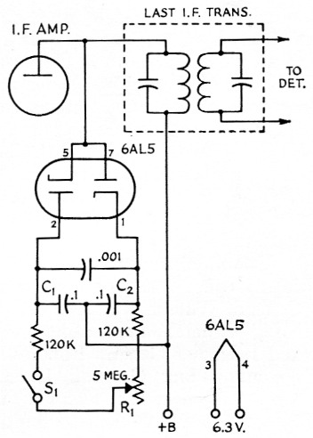
Fig. 1. Circuit of the i.f. noise limiter.
Capacitances are in µF. C1 and C2 are paper tubular. R1 is a 5 megohm control, linear taper.
The circuit can be added to most receivers without affecting their original performance except when S1 is closed. The exact frequency of the i.f. amplifier is relatively immaterial, and the circuit has been tested on both 455 and 2215 kc with comparable results. Its use to provide noise-limiting action in an automobile receiver should prove to be most effective, and the installation could be made without compromising the receiver's use for broadcast reception. The mechanics of the installation should be such that the leads to the i.f. transformer are as short as possible. If the threshold control R1 is necessarily mounted in a remote position, it should be connected through a length of flexible coax, such as RG-58/11. Preferably, it should be mounted as close to the 6AL5 tube as practical. If the builder is tempted to return the center tap of C1 and C2 to ground rather than to the B+ end of the i.f. transformer, he will discover a noticeable deterioration in performance.
The amount of use of any receiver feature is usually directly proportional to its practical effectiveness. In three years of operating a 75A-4 at K5ENB, the receiver's original noise limiter was switched on less than a total of ten minutes. Since installing the circuit under study, it has never been switched to the "off" position.
Notes
- Lamb, "A noise-silencing i.f. circuit for superhet receivers", QST, February, 1936.
- This is the ease with the author's 75A-4 receiver, in which, because of the particular circuit arrangement used, it is unlikely that any substantial amount of b.f.o. voltage is present in the primary of the last i.f. transformer. In other receivers this might not be so. In such case the h.f.o. voltage in the i.f. transformer primary would determine the limiting level on c.w. and s.s.b. signals, or at least put a "floor" under the limiting level. - Editor.
Walter J. Stiles, K5ENB/W7NYO.