U.H.F. coaxial s.w.r. bridge
A simple balanced bridge for 200 to 1300 Mc.
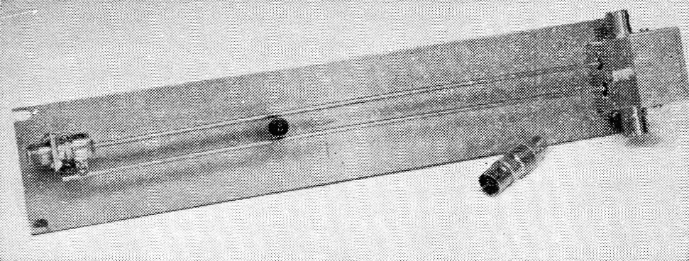
The standing-wave bridge built by W8FKC. Parallel line is a balun with an adjustable short (small black knob) for adjustment of the resonant frequency. Device in foreground is a laboratory standard 50-ohm load, though a suitable substitute can be made readily from low-cost components.
A standard laboratory instrument for measuring impedance and standing-wave ratio in the u.h.f. region is the slotted line, a device not generally available to amateurs. (A rare piece of surplus, the TS-56 A/AP, covering 300 to 1500 Mc, is sometimes found in amateur shacks.) Use of slotted lines is tedious and time-consuming compared to the s.w.r. bridge used at lower frequencies. The main goal of most amateurs is to adjust an unknown load such as an antenna to allow it to be fed through line having a low s.w.r. A balanced bridge is one of the simplest methods of doing this job, but there is little in amateur journals on the use of the s.w.r. bridge technique above 150 Mc. This need not be the case. A recent short article in a trade journal(1) suggests the use of a coaxial balun transformer feeding opposite arms of a symmetrical resistance bridge.
The major problem with a coaxial bridge circuit at u.h.f. is the elimination of residual phase unbalance in the bridge circuit itself. Most of those who have tried resistance bridge techniques as applied to h.f. have given up this approach at u.h.f. A balun transformer has the interesting property of providing equal amplitude, but out of phase voltages at its balanced end from a single coaxial source. This is precisely what is needed to feed a resistance bridge with coaxial line terminations.
The circuit diagram of the bridge is shown in Fig. 1. The author chose a 1:1 balun, whose length is adjusted to a quarter wavelength for the frequency in use by means of a sliding short across the line. This allows the bridge to be used over a wide frequency range merely by moving the position of the short. The balun can be any maximum length. Making it 16 inches overall permits operation down to about 200 Mc. Increasing the length to 21 inch will extend the range down to 144 Mc. Spacing of the balun, S, should be less than 0.1 wavelength at the highest frequency to be used. The one shown is spaced ¾ inch. This is a bit wide at 1300 Mc, but the bridge has a residual s.w.r. of only 1.05 at this frequency, when comparing equal terminations. At 220 and 432 Mc, the bridge gives essentially a perfect null; i.e., s.w.r. of 1.00 with equal terminations.
Conventional baluns of coaxial line (see ARRL Handbook or Antenna Book) may be used in making a bridge of this type for use on one band. If provision is made for detaching the barns, additional ones can be made up for other bands, but the sliding-short type used here is a more convenient and flexible approach. The balun made with a half-wave loop of coax gives a 4:1 impedance step-up, but it can be used in the same manner as the 1:1 balun shown.
The main construction feature to observe is to make the construction and wiring as symmetrical as possible. The bridge, exclusive of the balun, is built in a small Minibox, with the balun emerging from one side through holes insulated with sheet polystyrene. The holes should be at least 3 times the diameter of the balun tubing.
The balun is made of 1/8 or ¼ inch copper tubing. The impedance of the coaxial portion is not important, and it can be made by pulling any well-insulated wire through the length of the tubing. A length of small coaxial line, with its outer shield removed if necessary for fitting it in the tubing, may be used. Preferably the wire and its insulation should make a smooth fit inside the copper tube. The tubing that comprises the line should be kept bright, so that the sliding short will make good contact.
To use the bridge with full accuracy it is necessary to obtain a good coaxial standard. A fairly good one is the General Radio 874-WM which is a ½ watt 50 ohm termination good to about 5000 Mc. If this termination is used, General Radio coaxial fittings are necessary, or suitable adapters must be made for the bridge. (Type N or BNC fittings can be used on the bridge itself instead of the modified GR 874 B connectors used by the author.) A reasonably good termination can be made by soldering a ½ watt, 5 per cent, 51 ohm carbon resistor in a type N or BNC cable fitting.
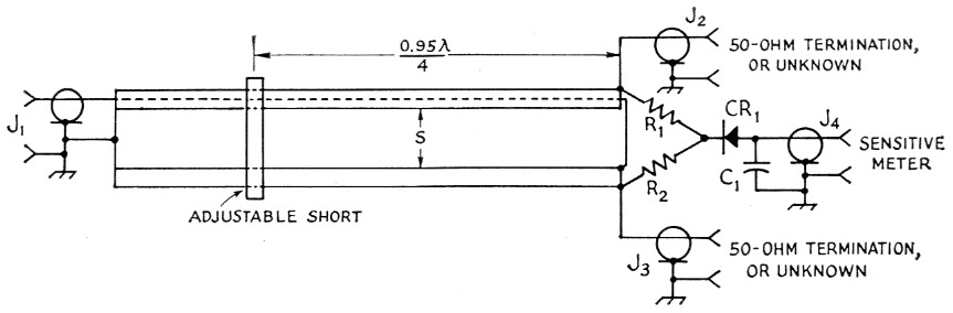
Fig. 1. Schematic diagram of the u.h.f. s.w.r. bridge. Balun, left, can be any length. Spacing, S, should be less than 0.1 wavelength at the highest frequency at which the bridge will be used. See text for other mechanical details.
| C1 | 100 pF button mica. |
| CR1 | 1N2IB diode. |
| J1,J2,J3,J4 | Coaxial fitting. J2 and J3 should preferably be type N or BNC. |
| R1,R2 | 50 ohm 1 % carbon. |
Operation
A signal generator or suitable low-power oscillator is coupled to the coaxial end of the balun and a termination plugged into one side of the bridge, leaving the opposite arm open circuited. The output of the signal generator is adjusted to give a deflection on a suitable indicating instrument such as a 100-ga. meter, with a transistor current amplifier if needed. A modulated signal source and an a.c. v.t.v.m. can also be used for indication. The sliding short is adjusted to give a maximum on the indicator. After this the short is locked in place and the termination moved to the opposite arm of the bridge. The indicator should read the same if the bridge is operating properly. If another matched load is now plugged into the open terminal a low reading or null will be indicated on the meter. The depth of the null is a measure of how low the s.w.r. is.
An unknown impedance such as an antenna system can now be connected to the open arm of the bridge. Since the bridge is balanced, either side can be used as the measuring terminal, with the opposite side as the standard. The unknown load is then pruned or adjusted to give the lowest possible reading on the indicator. The s.w.r. found by comparing the full-scale reading Vo (with one arm open circuited) with the null reading Vr (with the load connected). The s.w.r. is:
![]()
A plot of this equation is the same as the familiar graph of the reflection coefficient found in the Handbook and used with reflectometer-type s.w.r. devices at lower frequencies, if the full-scale reading is set at 1.0.
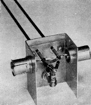
Interior view of the u.h.f. s.w.r. bridge, inverted from the position of the other photograph. Coaxial fitting supporting the crystal diode is used to connect a meter for reading diode current.
Bridge devices have their limitations, but they are certainly among the quickest and easiest s.w.r. measuring instruments to use. This particular model suffers from some hand-capacity effect, as the balun is hot for r.f. where it emerges from the box. This can be cured with a simple trough shield with an open top. Even without a shield, the bridge gives accurate s.w.r. indication. Performance of the bridge was compared with a TS-56 A/AP slotted line. Over the range of 320 to 1300 Mc. the bridge gives the same s.w.r. value as the slotted line with a precision of about t.05 when comparing the same load. This is more than sufficient for most amateur work with antennas, feed systems, and input-output circuit matching.
The author has found this device handy for adjusting the input and output circuits of cavity-type parametric amplifiers, for checking s.w.r. of noise generators, and for the usual antenna matching problems.
Notes
- Rice, "Use of a precision coaxial terminating resistor in a uhf swr bridge," Electrical Design News, June, 1959, p. 40.
R.W. Burhans, W8FKC.