Feeding grounded towers as radiators
80 meter operation with shunt drive.
Those who lack space for a horizontal antenna for 80 or 40 meters may be able to take advantage of this method of feeding the towers that support their higher-frequency beams or wire antennas.
With the diminishing sunspot activity, the higher-frequency bands are going dead earlier in the day, and the natural result is a swing to greater use of 40 and 80 meters. The big trouble for most hams wanting to use 40 and 80 meters is a lack of space for horizontal antennas. As a result, many more vertical antennas are being used. Many hams have towers or pipe masts to support rotary beams for 10, 15 or 20, or some combination of these bands. If such a tower or support is insulated at the bottom and is unguyed, the beam and rotor cables may be decoupled by a trap tuned to the operating frequency, and a tuning network inserted between the base and ground. If, as is more often the case, the tower is grounded and guyed with uninsulated guy wires, a somewhat different approach is necessary. This article is to describe how we fed two grounded towers at W9ERU for work on 80 meter.
First test
Tower Number One was a 64-foot self-supporting TV tower, tapering from about eighteen inches on a side at the bottom to about four inches at the top. The base was a large Y-shaped affair of 6-inch channel iron, held in the ground by three pipes running into concrete extending some four feet into the ground. The tower was guyed by one set of 3 wires, broken up with large egg insulators, to take the strain of a horizontal dipole, which was all this tower held up.
Now, this tower resembled, to some extent, one half of the driven element of the 20-meter beam in use at W9ERU; that is, it was approximately resonant at the desired frequency, was grounded at the base, and would have to be shunt fed. So the same feed system was tried that worked very well on the rotary beam - a modified gamma, or omega match. This type of feed system is illustrated in Fig. 1. A crude temporary lash-up proved that it would work, and a more finished job was installed. With this arrangement the s.w.r. was found to be reasonable (2 to 1 or less) over about 100 kc. of the 3.5 to 4 Mc band, and adjustments could be made to place this 100 kc. anywhere in the band. After proving the worth of this installation, we felt it desirable to use the circuit of Fig. 2 so that the antenna could be used at both ends of this band. When operating on the low end of the band a small relay is actuated, which adds capacitance as shown. The extra capacitance is required for work at the low end of the band. The relay and capacitors are mounted in a weatherproof metal box at the base of the tower as shown in the photographs.
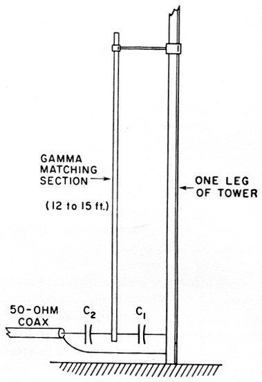
Fig. 1. Dimensions and values used by W9ERU in shunt-feeding a 64 foot tower. Capacitor types and ratings are discussed in the text. Capacitor connections shown are made as close as possible to bottom ends of tower leg and matching section.
| C1 | 400 to 500 pF |
| C2 | 250 to 350 pF |
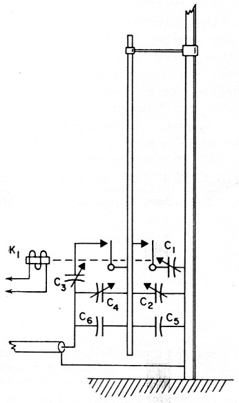
Fig. 2. This arrangement, left, makes it possible to adjust for low s.w.r. at two points in the band. See text for capacitor types and ratings. Capacitor connections shown are made as close as practicable to bottom ends of tower leg and matching section.
| C1,C2,C3,C4 | 120 pF variable. |
| C5 | 300 pF fixed. |
| C6 | 200 pF fixed. |
| K1 | Antenna change-over type relay. |
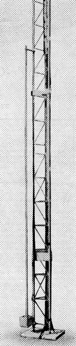
Lower portion of one of W9ERU's towers showing the gamma matching section.
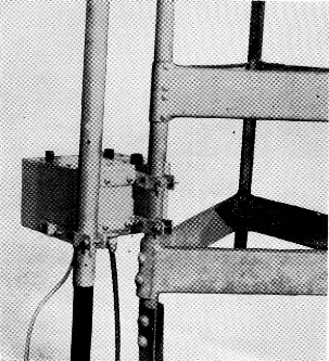
A close-up view showing the mounting of the tuning box. The polystyrene aircraft insulator supporting the gamma matching section may not be needed if the clamping arrangement is sufficiently rigid.
Ground system
The second installation at W9ERU was made on a 60 foot fold-over tower which holds up a full-size, three-element 20 meter beam with a 20-foot boom. This tower is about 12 inch on a side and is set in a block of concrete 2 feet square and 3 feet deep. It is guyed four ways at the hinge point near the midpoint of the tower, and these guy wires are insulated at top and bottom. A single set of capacitors was used and this tower was found to give satisfactory performance as a vertical radiator, but with considerably less band width for a satisfactory s.w.r. The narrow band width (about 25 kc.), was attributed to the fact that its resonant point is farther from the operating frequency than the first tower.
In an effort to improve the bandwidth a ground system was installed. This system consists of fifteen 66 foot lengths of No. 12 tinned copper wire connected to four ground rods, each 4 feet long, driven in at the base of the tower. The ground rods, tower legs and all inner ends of the ground wires were connected together. No detectable change was noticed when the ground system was installed - at 3.5 Mc, that is. On 20 meter there was a distinct difference in the performance of the beam - but that is another story. Either the tower was well grounded in the first place, or the radial ground system was not large enough to make any substantial change.
Forty meter
While both of these installations were made for use on 80 meters, there is no reason why such a system could not be made to work on 40, and it should result in good low-angle radiation so long as the tower and beam represent 5/8 wavelength or less. With lengths over 5/8 wavelength, a considerable lobe of high-angle radiation appears and results would probably not be too good. So far no effort has been made to use either tower at W9ERU for 40meter work, mostly because of bad weather and existence of a 60-foot vertical radiator already in use on this band (but fed at the center, 30 feet above ground).
Coaxial feedlines and rotator control lines for tower mounted beams should be carried down the tower and run underground from the base, and should pose no problem when installing the low-band feed system, since they should then be at the same potential as the tower at the same point. Coupling between the tower and metal objects in the near vicinity may affect the tuning of the omega match, but so long as these objects are not moved, the feed system should remain in adjustment. The bottom end of the omega rod is "hot" and care should be taken not to change conditions in the immediate vicinity, say within a two- or three-foot radius.
Construction
To try such a feed system, it is necessary to have an s.w.r. bridge, a source of r.f. power, metal tubing and capacitors, with the necessary brackets, insulators and box. Since it is not contemplated that an exact copy will be made, drawings and photographs of interior construction are not provided. For the gamma section, 1½ inch tubing was used, but smaller size could be employed and steel should work as well as aluminum. Double-spaced capacitors were used for the variable units, while 3000 volt mica and 7500 volt ceramic capacitors were used for the fixed units. One of the boxes shown in the photographs is 5 by 6 by 9 inch, while the other is 6 by 6 by 6 inch. It is necessary to insulate from the box those capacitors whose rotors are not shown connected to the grounded tower. The clamp holding the lower end of the omega rod to the box must be insulated too, of course. The clamps holding the box to the base of the tower are bolted solidly to the box. The tuning-capacitor shafts are passed through tight-fitting rubber grommets to prevent water seepage, and small holes (1/8 inch) are provided in the bottom of the box to drain condensation. The whole installation is sprayed with clear acrylic or polystyrene dope to make it as waterproof as possible.
The radiation pattern will differ from a half-wave horizontal or trap doublet, but if you have these already up, you don't really need this antenna, and you will probably try it only to see if it will work. It will!
Gene Hubbell, W9ERU.